background image

10

11

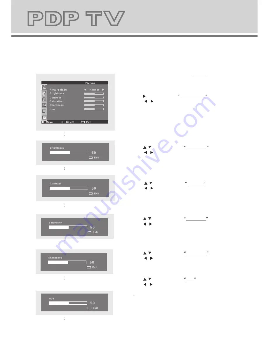
Picture 

1.Press the 

MENU

  button to enter the Picture menu screen.

   (Fig.1-1)

4.Press the  

/

 button to select Contrast

.

   Press  the     /     button to adjust the value of 
   contrast on the control bar. (Fig. 1-3)

5.Press the 

/

 button to select Saturation

.

   Press the     /     button to adjust the value of 
   saturation on the control bar. (Fig. 1-4)

6.Press the 

/

 button to select Sharpness

.

   Press  the     /     button to adjust the value of 
   sharpness on the control bar. (Fig.1-5)

7.Press the 

/

 button to select Hue

.

   Press  the    /     button to adjust the value of  hue on
    the control bar. (Fig. 1-6)
  

 Note

Only when the color system of input video signal 

               is NTSC, this option is available.

8.Press the 

MENU

 button to return to the upper menu.

2.Press the     button to select

Picture mode

.

   Press the      /     button to set the picture mode 
   ( Normal, Soft, Vivid or User).

3.Press the 

/

 button to select Brightness

.

   Press  the     /     button to adjust the value of 
   brightness on the control bar.(Fig.1-2) 

Sound 

7.Press the 

MENU

 button to return to upper menu.

1.Press the 

MENU

 then the 

/

button to enter the

   Sound menu screen.(Fig.2-1)

2.Press the     button to select

Sound mode

.

   Press the     /     button to set the sound mode 
   ( Normal, News, Movie or User).

3.Press the 

/

 button to select Volume

.

   Press  the     /     button to adjust the value of 
   volume on the control bar.(Fig.2-2) 

4.Press the 

/

 button to select Bass

.

   Press  the    /     button to adjust the value of 
   bass sound on the control bar.(Fig.2-3) 

5.Press the 

/

 button to select Treble

.

   Press the     /     button to adjust the value of 
   treble on the control bar.(Fig.2-4) 

6.Press the 

/

 button to select Balance

.

   Press  the    /     button to adjust the value of 
   balance on the control bar.(Fig.2-5) 

Fig.1-1)

Fig.2-1)

Fig.1-2)

Fig.2-2)

Fig.1-3)

Fig.2-3)

Fig.1-4)

Fig.2-4)

Fig.1-5)

Fig.2-5)

Fig.1-6)

MENU

MENU

MENU

MENU

MENU

MENU

MENU

MENU

MENU

MENU

MENU

Summary of Contents for PDP TV

Page 1: ...Waste electrical products must not be disposed of with household waste This equipment must be returned to the retail store for safe disposal or it can be taken to your local recycling centre ...

Page 2: ...USER MANUAL ...

Page 3: ...lication instruction of remote control Connecting to antenna or TV radio network Connecting digital TV Set Top Box Picture Sound Function TV SOURCE Connection to exterior devices Trouble shooting 3 3 4 5 7 8 9 9 10 11 12 13 PC 14 Advance 14 15 16 17 PDP TV Panel continued 6 ...

Page 4: ... CAUTION TO REDUCE THE RISK OF ELECTRIC SHOCK DO NOT REMOVE COVER OR BACK REFER SERVICING TO QUALIFIED SERVICE PERSONNEL WARNING RISK OF ELECTRIC SHOCK DO NOT OPEN Before using this product read and follow all warnings and instructions This product is not intended for use by young children or infirm persons unless they are adequately supervised by a responsible person to ensure that they use this ...

Page 5: ... repair Turn off and disconnect the power cable before cleaning or storing this product Ensure this product does not get wet or splashed Only use the A C power adapter supplied with your product or a replacement recommended by a qualified technician Don t do Do not place naked flames such as lighted candles on the unit Do not place objects filled with liquids such as vases on the unit Do not insta...

Page 6: ...5 PDP TV Panel 1 Volume control buttons VOL 2 Channel selection buttons CH 3 Menu Confirm button MENU 4 Input source selection button SOURCE 5 Power Standby button ...

Page 7: ...DMI e AV2 L R Color difference component input terminal and AV2 input terminal f AV1 L R YPBPR Color difference component input terminal and AV1 input terminal and audio input terminal g S VIDEO Color and brightness separation input terminal h SCART IN SCART input terminal suit for European export machine i VHF UHF Antenna close circuit TV network port 75 Ohm VHF UHF j Power On Off Power On Off b ...

Page 8: ... P STD SOURCE DISPLAY S STD SLEEP MUTE 1 4 7 2 5 8 0 3 6 9 MENU V O L PROGRAM Power button Numeric button Channel setup Picture mode button Sound mode button Right Down Channel selection button Up LEFT Signal source selection button Volume adjusting button Sleep button Mute button Return channel button Program information Main menu NICAM function button ...

Page 9: ...YPBPR PC HDMI P STD P STD button setting the picture mode for TV AV SVIDEO YPBPR PC HDMI input mode S STD S STD button setting the sound mode DISPLAY Press display button to view the current channel Press again to remove channel information MENU OSD menu button to enter the TV setup menu UP Down Up and down button of OSD menu To change the OSD menu items and to increase or decrease the channel Lef...

Page 10: ...d If other coaxial cable is used there may be noise and image disturbances Indoor antenna is NOT recommended for this TV quality In order to receive digital TV programs a digital TV STB must be connected to the rear of the PDPTV Connect the coaxial cable connector to The output terminal The antenna input terminal For further instruction refer to the receiver instruction manual Connecting digital T...

Page 11: ...f sharpness on the control bar Fig 1 5 7 Press the button to select Hue Press the button to adjust the value of hue on the control bar Fig 1 6 Note Only when the color system of input video signal is NTSC this option is available 8 Press the MENU button to return to the upper menu 2 Press the button to select Picture mode Press the button to set the picture mode Normal Soft Vivid or User 3 Press t...

Page 12: ...Press the button to adjust the value of volume on the control bar Fig 2 2 4 Press the button to select Bass Press the button to adjust the value of bass sound on the control bar Fig 2 3 5 Press the button to select Treble Press the button to adjust the value of treble on the control bar Fig 2 4 6 Press the button to select Balance Press the button to adjust the value of balance on the control bar ...

Page 13: ...ur minute part of Current time Off Time On Time and On Channel Press the button to set the value of selected item 6 Press the MENU button to return to upper menu 1 Press the MENU then the button to enter the Function menu screen Fig 3 1 2 Press the button to select Language Press the button to set the desired OSD language Fig 3 1 Fig 3 2 3 Press the button to select Blue Back ground Press the butt...

Page 14: ...nd 12 Fig 4 5 Press the button to select Channel 1 Press the button to set the letter to 3 Press the button to select Channel 2 Press the button to set the letter to 12 Press the button to select Swap Press the button exchange finished 3 Press the button to select Manual Tune Press the button Manual Tune screen appears Press the button to select Channel Search or Store in turn Press the button to ...

Page 15: ... Adjust Press the button the unit will adjust above options automatically Note This menu is available only when the SOURCE menu is set to PC 7 Press the MENU button to return to upper menu PC MENU Advance 2 Press the button to select Scale Press the button to set the proper display scale 16 9 4 3 3 Press the button to select 3D NR Press the button to set the 3DNoise reduction setting of pictures H...

Page 16: ...tton to adjust the OSD menu duration time on the screen 7 Press the button to select PIP Press the button to enter PIP setting screen Fig 5 2 Fig 5 2 Move OFF o nd Main MENU 7 1 Press the button to select PIP Mode Pres s the button to select the PIP Mode 7 2 Press the button to select SUB Source Pres s the button to select the SUB Source 7 3 Press the button to select PIP Size Pres s the button to...

Page 17: ... a common Audio in 2 AV2 use a common Audio in 3 Y PB PR of DVD is corresponding to Y PB PR of PDP TV R2 L2 Av2 R1 L1 Av1 R2 L2 Av2 4 Scart to Scart from a VCR 5 DVI to HDMI and using the PC audio 6 PC to VGAalso using the PC audio 7 AV IN and YPBPR from a DVD HDMI VGA PC AUDIO Y PB PR R1 L1 Av1 AUDIO HDMI DVI R L HDMI VGA VGA Y PB PR SCART SCART SCART ...

Page 18: ...eral dead pixels on the panel are deemed acceptable by the industry standards In line with manufacturers and would not mean that the panel is faulty Few dead pixels on the panel will not be changed or refunded We hope you will understand that the product that corresponds to this standard is regarded as acceptable NOTE ...

Reviews: