background image

INP-TN5A1634-E 

21

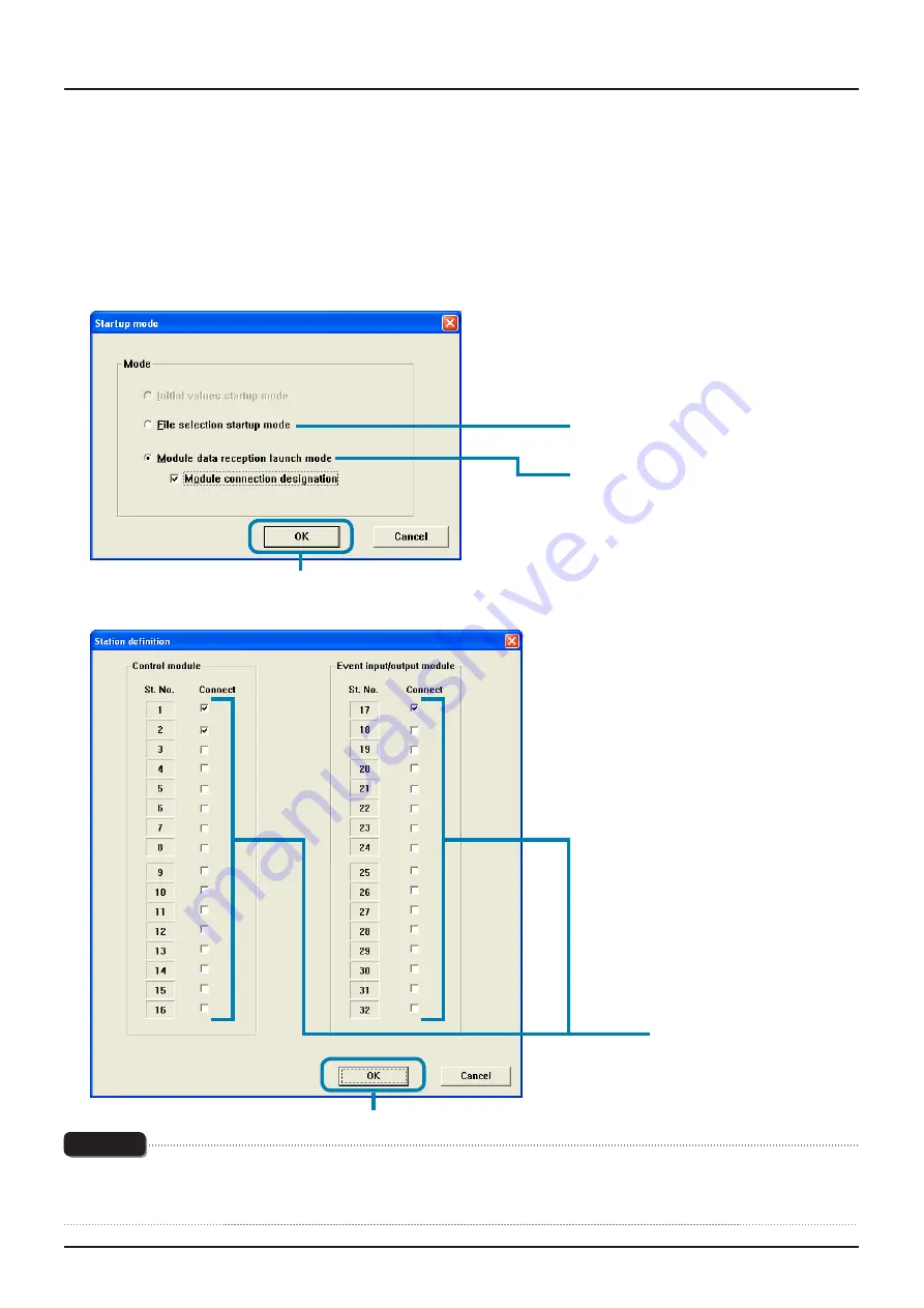
Reading the setting by selecting the Station No. of the module-type temperature 
controllers connected

This method is not available when selected the “Enhanced comm module [Mitsubishi's programless comm]”, “Profibus comm 
module [Profibus comm]”, “Ethernet comm module [Ethernet comm]” on the “module type selection”.

1

  Select “Module data reception launch mode” on the “Startup mode” screen, check “Module connection designation,” and 

click [OK].

(3) Click.

(1) Click.

(2) Check.

2

  Check the St No. of the module-type temperature controller to be read on the “Station definition” screen, and then click [OK].

(1) Check.   

*1

(2) Click.

Note

Do not check the ST No. of the controller that is not connected.  Otherwise a communication error occurs.  The “communication 
error” message does not appear in this case.  (The reading from the module-type temperature controller connected is performed 
normally.)

*1: Select from the Station Numbers of "Control 

module" with Analog module.

Summary of Contents for PUM

Page 1: ...nual Contents 1 About the copyright of this software 3 2 Outline 3 3 Operating environment 3 4 Installing uninstalling the software 4 Installation 4 Uninstallation 6 5 Connecting your PC to the module...

Page 2: ...2 INP TN5A1634 E...

Page 3: ...mperature controllers The PV SV and MV trend can also be displayed as an auxiliary tool for tuning the module type temperature controllers Unless otherwise specified the parameter loader for module ty...

Page 4: ...ake sure to conduct to uninstall it Installation Install the parameter loader for PUM on your PC 1 Open the PUM loader folder which was downloaded and double click PUMLoader Installer exe Note Please...

Page 5: ...ck To stop installation click Cancel Note When you use Windows7 do not install the parameter loader to C Program Files Otherwise parameter loader for PUM may not be operated properly 5 Confirm the ins...

Page 6: ...top installation click Cancel 7 Click Finish Uninstallation 1 Windows XP Control panel C Program Add Delete from the start menu to uninstall the software 2 Windows 7 Select Control panel C Program fro...

Page 7: ...he parameters of the enhanced communication module connect the loader connecting cable to the loader communication port of the enhanced communication module Connection with RS 232C Provide the optiona...

Page 8: ...e to turn off the power of the module type temperature controllers before making connections 4 Set the station number configuration switches of the connected module type temperature controllers as 1 2...

Page 9: ...8 Do1 Do2 Do3 Do4 Do5 Do6 Do7 Do8 STATION 4 3 2 1 0 F E D C B A 9 8 7 6 5 STATION 4 3 2 1 0 F E D C B A 9 8 7 6 5 LOADER PUM E PWR COM Di1 Di2 Di3 Di4 Di5 Di6 Di7 Di8 Do1 Do2 Do3 Do4 Do5 Do6 Do7 Do8 W...

Page 10: ...9 8 7 6 5 LOADER PUM A PWR COM OUT1 OUT2 OUT3 OUT4 STATION 4 3 2 1 0 F E D C B A 9 8 7 6 5 STATION 4 3 2 1 0 F E D C B A 9 8 7 6 5 PWR BUS RX1 TX1 RX2 TX2 LOADER PUM C LOADER PUM A PWR COM OUT1 OUT2 O...

Page 11: ...aunched and click OK If you click Cancel parameter loader for PUM is end 2 Click 1 Select the module type of temperature controller to be launched 2 Startup mode is indicated Screen of control event a...

Page 12: ...tart up Initial values startup mode P 13 Module data reception launch mode P 19 File selection startup mode P 17 Note In module type selection screen in case you select the module type selection diffe...

Page 13: ...e setting Make sure to conduct this function under a situation where PUM is not connected to PC 1 In Startup mode screen select Initial values startup mode and click OK Screen of control event analog...

Page 14: ...ation No to be set model code setting screen appears Set the last 10 digits of type code and click Check button When registration is completed type code will be indicated at A in model code setting an...

Page 15: ...ss communication screen of station definition is not indicated and model code setting appears Enhanced communication module Mitsubishi program less communication has the fixed model code therefore do...

Page 16: ...e setting appears ProfiBUS communication module ProfiBUS communication has the fixed model code therefore do not change the model code setting and just click Check button and then click OK button afte...

Page 17: ...ng file stored previously as follows 1 Select File selection startup mode on the Startup mode screen and then click OK The display screen of the control event analog module on start up 2 Click 1 Click...

Page 18: ...N5A1634 E 2 On the File selection startup mode screen select the file or the parameter setting stored previously and then click Open 2 Click 1 Select The PUM loader PUM parameters Support screen appea...

Page 19: ...cted module type temperature controllers as follows 1 On the Startup mode screen select Module data reception launch mode and then click OK The display screen of the control event analog module on sta...

Page 20: ...s the Esc key on the keyboard to cancel reading Note Approximately 20 seconds are required to read the parameter settings per module type temperature controller Do not perform other communication oper...

Page 21: ...he Startup mode screen check Module connection designation and click OK 3 Click 1 Click 2 Check 2 Check the St No of the module type temperature controller to be read on the Station definition screen...

Page 22: ...he keyboard to cancel reading Note Approximately 20 seconds are required to read the parameter settings per module type temperature controller Do not perform other communication operations while the s...

Page 23: ...the File menu Click 2 Set required items on the Initial setting screen and then click OK Click Select COM port Baud rate 19200 Fixed Data length 8 Fixed Parity None Fixed Stop bit 1 Fixed Connection C...

Page 24: ...INP TN5A1634 E Note The Online Offline setting can be made only when startup is performed by selecting Module connection designation on the Startup mode screen The setting is always Offline on start...

Page 25: ...ers can be checked trend can be displayed and parameters can be copied PUM loader PUM Parameters Support screen On the PUM loader PUM Parameter Support screen parameter tree is displayed on the left a...

Page 26: ...P TN5A1634 E The display screen of the enhanced comm module Mitsubishi s programless comm on start up Parameters are displayed Parameter tree is displayed Set values are displayed Blank cell cannot be...

Page 27: ...INP TN5A1634 E 27 The display screen of the enhanced comm module Profibus comm on start up Parameters are displayed Parameter tree is displayed Set values are displayed Blank cell cannot be set...

Page 28: ...ced comm module Ethernet comm on start up Parameter are displayed Parameter tree is displayed Set values are displayed Blank cannot be set Device size setting for setting monitor area during mapping c...

Page 29: ...ght double click the setting to be changed 1 Select the parameter group from the Parameter tree 2 Double click the setting to be changed 2 Set a desired value on the Please set the value window and th...

Page 30: ...be set Some values banned setting are included in the setting range displaied in the enhanced communication module Refer to the detailed parameter manual in the relevant parameters P 36 about the val...

Page 31: ...TN5A1634 E 31 Favorite Frequently used parameters can be set in Favorite in the parameter tree screen on the left side Up to 200 parameters per module can be registered Displays parameters set in Favo...

Page 32: ...rameters Support screen on P 25 right click the parameter you want to register in Favorite and then click Favorite Add Delete 2 Click Press the F2 key on the keyboard while a parameter is selected on...

Page 33: ...e Favorite tree on the PUM loader PUM Parameters Support screen on P 25 and then click Favorite Add Delete 2 Click 1 Right click Press the F2 key on the keyboard while a parameter is selected on the p...

Page 34: ...Favorites Files Save A from Data D menu Save As dialog appears input a file name and then click Save S Open favorites file 1 In the screen of PUM Parameters Support P 25 select the Favorites File Ope...

Page 35: ...lay ON and OFF Parameter display on the setting screen on the right side can be changed between ON and OFF Parameters set as OFF are not displayed on the setting screen on the right side Parameters se...

Page 36: ...M loader PUM Parameters Support screen on P 25 and click Display ON OFF 2 Click 1 Right click You can also press the F4 key on the keyboard while the parameter is selected on the parameter tree screen...

Page 37: ...de 1 Select a parameter from the parameter tree screen on the left side of the PUM loader PUM Parameters Support screen on P 25 and then right click the setting that displays a related parameter on th...

Page 38: ...n the Relevant parameters screen Displays related parameters Setting change can also be made Click to display detailed manual of the parameter To display detailed manual of the parameter Click Manual...

Page 39: ...ged the change can be written into the module type temperature controller 1 Select Initial setting on the File menu of the PUM loader PUMP Parameters Support screen on P 25 Click 2 Select Online on th...

Page 40: ...hanged parameter are read Reading takes approximately 20 seconds per module type temperature controller If a parameter that changes its value when processing is exited such as auto tuning start comman...

Page 41: ...rom the Tool menu of the PUMP loader PUM Parameters Support screen on P 25 Click 2 Check the composition of the module type temperature controller on the Module composition screen Display screen of th...

Page 42: ...de serial code It displays the connected module type temperature controller It displays St No for enhanced communication Note that this is different from the St No of the loader communication port Not...

Page 43: ...troller currently edited can be checked 1 Select Model composition from the Tool menu of the PUM loader PUM Parameters Support screen Click 2 Select a desired model code on the Display model code scre...

Page 44: ...44 INP TN5A1634 E Display screen of the enhanced communication module on start up Click...

Page 45: ...ool menu of the PUM loader PUM Parameters Support screen on P 25 Click 2 Set required items on the Trend selection screen and then click Trend Disp 2 Set the duration from the time when sampling is co...

Page 46: ...s required select time for display format in Excel cell format setting change it into desired display format and then save the data The first data at the start of trend display may differ from the act...

Page 47: ...the Enhanced comm module Mitsubishi s programless comm Enhanced comm module Profibus comm Enhanced comm module Ethernet comm on the module type selection Copying between channels 1 Select Parameter co...

Page 48: ...indow Click To cancel parameter copying Click Cancel In Ch copy the data is copied only within the station specified in From St Ch No Note Make sure that the channel No on the left side becomes smalle...

Page 49: ...Select Parameter copy C from the Tool T menu of the PUM loader PUM Parameters Support screen on P 25 Click 2 Click the St copy tab on the Parameter copy screen Click To copy event module parameters b...

Page 50: ...ncel the parameter copy Click Cancel Follow the same procedure for copying parameters between stations Event Note Be sure not to specify station No that has not been defined Otherwise an erroneous val...

Page 51: ...CTRL C or right click to indicate the Menu and select Copy C 2 Paste Pate the parameter copied by copy function Select the parameter to be pasted Press CTRL V or right click to indicate the Menu and s...

Page 52: ...or copy or paste either way it is undoable for one time only 1 Press CTRL Z or right click to open Menu and click UnDo Z Undo function can conduct to return the last changed part to previous action re...

Page 53: ...used when you select Enhanced communication module Mitsubishi program less communication or ProfiBUS communication module 1 Click Station No change C from Data in main menu or right click in parameter...

Page 54: ...lect the changed station No and then click OK Note If you set the existing station No to the station No after change station No is overwritten Additionally station No before change will be deleted UnD...

Page 55: ...ed communication module Mitsubishi program less communication or ProfiBUS communication module ProfiBUS communication or Ethernet communication module Ethernet communication this function can not be u...

Page 56: ...ndicate the menu and click Station No Delete X 2 To delete the station number dialog is indicated select the station No and click OK 3 When confirmation message to delete the station appears click YES...

Page 57: ...munication Enhanced comm module Ethernet comm Setting area 1 to 712 Monitor area 1 to 712 ProfiBUS communication module ProfiBUS communication Output area 1 to 108 Input area 1 to 108 1 Select the par...

Page 58: ...compare current setting parameter to initial data or connected PUM Compare initial data 1 Click Compare Initial data I from Data in the menu or right click to indicate the menu and then click Compare...

Page 59: ...5A1634 E 59 Compare Module Data 1 Click Compare Module data M from Data in the menu or right click to indicate the menu and then click Compare Module data M 2 Select station numbers to compare and cli...

Page 60: ...be compared to PUM When you press ESC key during operation of comparison operation will stop in the middle of comparison In this case parameter may not be indicated properly Upload P 62 the current pa...

Page 61: ...UM Parameters Support screen on P 25 Click 2 Set necessary items on the Parameter list screen and then click Print or CSV Disp Select a module type temperature controller to be printed or displayed No...

Page 62: ...n A4 paper in vertical orientation fixed The setting display of the PUM parameter loader and the display of the printing CSV output result may not be the same Example If the PUM parameter loader displ...

Page 63: ...PUM data transmit U from the Data D menu of the PUM loader PUM Parameters Support screen on P 25 Click Proceed to2 when selected the control event analog on the module type selection Proceed to3 when...

Page 64: ...type temperature controllers to be uploaded on the Station definition screen and then click OK 1 Check 2 Click Proceed to4 Note Do not check the box of the module not connected 3 Click OK on the PUM l...

Page 65: ...the Save as screen and then click Save 1 Select the file in which the parameter setting is to be saved 2 Click Note Approximately 20 seconds are required for uploading per module type temperature con...

Page 66: ...PC PUM data transmit D from the Data D menu of the PUM loader PUM Parameters Support screen on P 25 Click Proceed to2 when selected the control event analog on the module type selection Proceed to3 w...

Page 67: ...re controllers to be downloaded on the Station definition screen and then click OK 1 Check 2 Click Note Do not check the box of the module not connected To cancel downloading Click Cancel 3 Click OK o...

Page 68: ...ding Do not turn off the power of the module type temperature controller while downloading Do not pull out the loader connection cable while downloading Do not carry out downloading with the auto tuni...

Page 69: ...pen from the Data menu of the PUM loader PUM Parameters Support screen on P 25 Click 2 Click OK on the PUM loader screen Click OK to save the parameter setting currently selected and go to 3 Click Not...

Page 70: ...the parameter setting is to be saved on the Save as screen and then click Save S 1 Select the file in which the data is saved 2 Click 4 Select the desired file on the Open screen and then click Open 2...

Page 71: ...ter settings can be saved in a file 1 Select Save from the Data menu of the PUM loader PUM Parameters Support screen on P 25 Click 2 Select the file in which the parameter settings are to be saved on...

Page 72: ...rom the File menu of the PUM loader PUM Parameters Support screen on P 25 Click 2 Click Yes on the Exit window Click Yes to save the parameter setting currently selected and go to 3 Click Not to save...

Page 73: ...run up to 4 PUM loaders at the same time When you run the 2nd PUM loader message appears and click YES Y PUM loaders will be multi launched Note When you conduct the multi launcher function of PUM loa...

Page 74: ...tion between modules Parameters can not be changed RS 485 communication permission is set to Read only Change the setting to Readable Writable The parameter input value tried to write the value out of...

Page 75: ...e display is not updated Click the parameters on the parameter tree display on the left side of the screen to update the tree Communication port does not open is displayed Multiple communication progr...

Page 76: ...responding parameter version Unsupported Use the parameter version marked Character string such as 01A Operable parameter loader version differs depending on the revision No of PUM series Check the re...

Reviews: