– 6 –
2.3 Precautions in wiring connection
•
For the thermocouple sensor type, use thermocouple compensation wires for wiring.
•
Keep input lines away from power line and load line to avoid the influence from noise induced.
•
For the input and output signal lines, be sure to use shielded wires and keep them away from each
other.
•
If a noise level is excessive in the power supply, the additional installation of an insulating transformer
and the use of a noise filter are recommended. (example: ZMB22R5-11 Noise Filter manufactured by
TDK)
Make sure that the noise filter is installed to a place such as a panel that is properly grounded. The
wiring between the noise filter output terminal and the instrument power supply terminal should be
made as short as possible. None of fuses or switches should be installed to the wiring on the noise
filter output side because the filter effect will be degraded by such a installation.
•
A better anti-noise effect can be expected by using stranded power supply cable for the instrument.
(The shorter the stranding pitch is, the better the anti-noise effect can be expected.)
•
A setup time is required for the alarm output when the power is turned on. If the alarm output is used
as a signal for an external interlock circuit, use a delay relay at the same time.
•
Use the auxiliary relay since the life is shortened if full capacity load is connected to the alarm output
relay.
•
If inductive load such as magnetic switches connected as a alarm output load, it is recommended to
use Z-Trap manufactured by Fuji Electric to protect a contact from switching serge and keep a longer
life.
Model :
ENC241D-05A (power supply voltage: 100 V)
ENC471D-05A (power supply voltage: 200 V)
Where to install :
Connect it between contacts of the alarm output.
Example)
2.4 Requirement for key operation/operation in abnormalities
•
A display of UUU or LLL will appear in case of a break in the input. Be sure to turn off the power when
a sensor is replaced.
•
Do not turn OFF the power for at least five (5) seconds if the alarm set value or any parameter was
changed.
2.5 Others
•
Do not use organic solvents such as alcohol and benzine to wipe this controller. Use a neutral deter-
gent for wiping this product.
•
Do not bring any mobile phone close to the main unit (50 cm). Malfunction will occur.
•
Noise may be produced if this equipment is brought close to a radio. Use this equipment as fully
spaced apart from radios.
•
Do not push the display unit (LCD) on the front face of this equipment with force. Observation of the
display (LCD) will become hard.
•
This equipment issues an LCD as the front display. There are cases where the display can be hardly
observed at a slant because of the characteristics of LCD.
•
Observation of the display (LCD) will become hard when the ambient temperature drops to a level
close to 0
°
C.
18
9
15
17
16
12 13 14
6
7
8
3
4
5
10 11
1
2
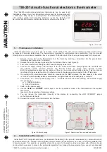
Z-Trap connection