– 2 –
2-2
Cautions when Attaching to the Panels
•
Insert the controller unit into the panel cutout from the front, and then put the mounting
bracket from the rear. The mounting bracket should be pushed in until the controller is
securely fixed to the panel. If there is a slight gap remaining, gently tighten the two screws
until the gap disappears.
(Make sure not to over tighten the screws, as doing so may result in the mounting bracket
separating from the stopper.)
•
The front of this equipment is waterproof in compliance with NEMA-4X standards (IP66-
equivalent).
To effect waterproof, the included packing is shall be attached between the controller and
the panel according to the guidelines below. (Incorrect attachment may cause the equip-
ment to lose its waterproof capabilities.)
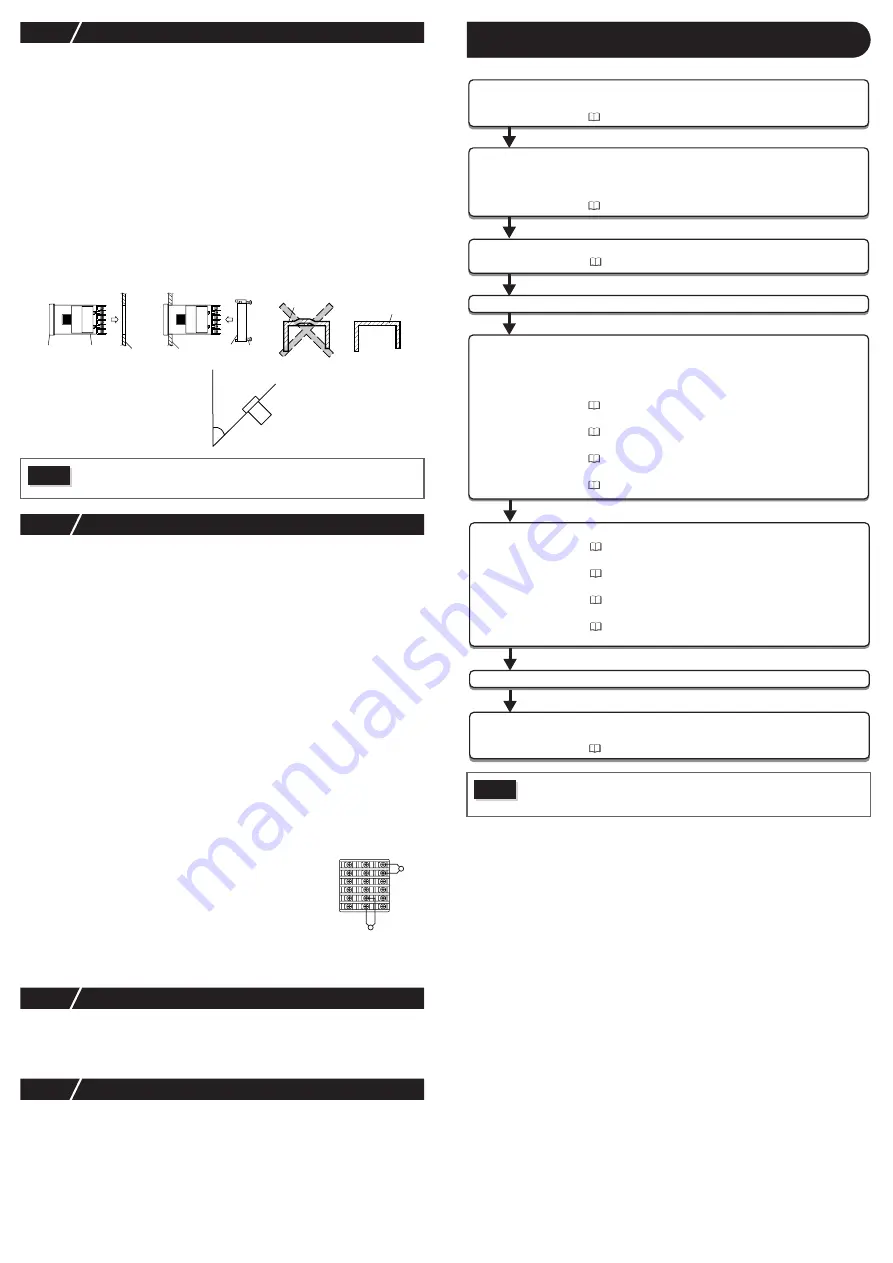
(1) As shown in Fig. 1, insert to the panel after attaching the packing to the equipment
case.
(2) As shown in Fig. 2, tighten the fixture screws so that no gaps can remain between the
equipment face, the packing and the panels. Once finished, confirm that there are no
changes in shape such as displaced or improperly-fitted packing, etc. as shown in
Fig. 3.
•
If the panel does not have enough strength, gaps may develop between the packing and
the panel to lose waterproofing capabilities.
2-3
Cautions for Wiring
•
For thermocouple input, use the designated compensation lead; for resistance bulb input,
use wires with small lead wire resistance and without any resistance difference among the
three wires.
•
To avoid noise conductor effects, input signal wires should be separated from electric
power lines or load lines.
•
Input signal wire and output signal wire should be separated each other. And both should be shield
wire.
•
If there is a lot of noise from the power source, adding an insulation transducer and using a
noise filter is recommended.
(Example: ZMB22R5-11, noise filter Maker: TDK)
Always attach a noise filter to a panel that is grounded securely, and keep the wiring
between the noise filter output side and the measuring equipment power terminal wiring
to a minimum length.
Please do not attach fuses and switches, etc. to the noise filter output wiring, otherwise the
filter’s effectiveness will be decreased.
•
Twisting the power wires is effective when connecting the wires. (The shorter the pitch of
the twist, the more effective the connection is against noise.)
•
If there is a function of heater current detection, heater wires and power wires should be
connected with same power line.
•
Operation preparation time is required for the contact output when power is turned on. If
using it as a signal to an external interlock circuit, please couple it with a delayed relay.
•
Concerning the output relay, connecting the maximum rated load will shorten the prod-
uct’s life; so please attach an auxiliary relay. If the output operation frequency is high,
selecting a SSR/SSC drive output type is recommended.
[Proportionate cycles] Relay output: 30 seconds or more, SSR/SSC drive output: 1
second or more
•
When inductive loads such as magnetic opening/closing equip-
ment, etc. as relay output equipment are connected, use of
“Z-trap,” manufactured by Fuji Electric Device Technology Co.,
Ltd., is recommended in order to protect the contacts against
opening/closing surges and to ensure long-term use.
Model names :
ENC241D-07A
(For 100V power voltage)
ENC471D-07A
(For 200V power voltage)
Attachment position : Please connect between the relay
control output contacts.
(Refer to Fig. 4.)
2-4
Key Operation Cautions/Error Operations
•
The alarm function does not work properly when an error takes place unless the settings
are made correctly. Always verify its setting before operation.
•
If the input wiring breaks, the display will read "
U
U
U
UU
U
U
UU
U
U
UU
U
U
U
". When replacing the sensor, always
turn the power OFF.
2-5
Others
•
Please do not wipe the equipment with organic solvents such as alcohol or benzene, etc.
If wiping is necessary, use a neutral cleaning agent.
•
Do not use mobile phones near this equipment (within 50 cm). Otherwise a malfunction
may result.
•
Trouble may occur if the equipment is used near a radio, TV, or wireless device.
For Proper Usage
Caution
•
In order to aid heat dissipation, do not block the sides of the equipment.
•
Do not block the air vents on the upper part of the terminal.
Fig. 3
Packing
Packing
Case
Case
(Bad)
(Good)
α
= 0 to 30
°
Fig. 1
Fig. 2
Screw
Mounting
bracket
Unit
Unit
Front
Case
Panel
Panel
Standard: vertical attachment
(horizontal position attatchment)
If attached at an angle, the maximum
gradient is a 30° downslope.
Fig.4 Attachment position
of Z-Trap
(Example)
13
16
17
18
14
15
7
8
10
11
12
9
1
2
4
5
6
3
Caution
Wait 30 minutes for the controller to stabilized thermally. Operations such as
measurements should be taken after the equipment has been on for 30 min-
utes or more.
Confirmation of model code
Please confirm that the model delivered matches your order.
"12 Model Specifications" (page 19)
2
Wiring Connection
Terminal connections diagram
"4 Wiring" (page 4)
3 Display and Operations
4 Parameter List
5 Functions of the Temperature Controller
Changing set value
Basic Operation Methods
Parameter List
Input/Output/Control
"5 Display and Operations" (page 5)
"5 Display and Operations" (page 5)
"6 Parameter List" (page 6)
"7 Functions" (page 10)
Turn Power On
6 Advanced Usage
Setting of input sensor and input range
Selecting control method
Controlling through auto-tuning
Automatic setting parameters
"8-1 Input Setting" (page 17)
"8-3 Control Setting" (page 17)
"7-6 Auto-tuning" (page 11)
"7-3 Fuzzy PID Control", "7-4 Self-tuning Control" (page 10)
7 Error Indications
Display during equipment error
"9 Error Indications" (page 18)
Operation
1 Installation and Mounting
External dimensions
• Panel cut dimensions
• Mounting the panel
"3 Installation and Mounting" (page 3)


