7
Before installation/maintenance, the tractor and mower should be
stationary with the hydraulic lift system in a neutral position and the
ignition key removed.
On a flat area of ground lower the three point linkage on the tractor to its
lowest position. Attach the mower to the tractor using the three point
linkage pins and linch pins:
Installation Overview
With the mower
’
s rear roller on the ground, adjust the length of the top
link arm so that the skids at the side of the mower are parallel with the
ground.
To set correct cutting height, rotate the blade rotor by hand, so they hang
vertically towards the ground. There should be a clearance of at least 5cm
between the blades and the ground. To increase the blade clearance and
cutting height for rough ground or long grass, raise the tractor
’
s hydraulic
lift arm or adjust the rear roller and skids on the mower.
The working speed of the mower should be at a walking pace of 2 to 5
mph. Overgrown grass/weeds should be cut at a much slower pace to
avoid damage to the mower.
Check the oil level in the gearbox, the tension of the drive belts and
tightness of all bolts, nuts and screws. Lubricate all grease points including
PTO drive shaft. Attach the PTO drive shaft and ensure locking pin is
secure on both the tractor and mower sides. Attach the chain to a secure
point on the tractor/mower. Ensure all safety guards are in place.
Always
replace worn or damaged
PTO drive shafts.
Operate the mower in a low gear range, keep the PTO output at 540 rpm.
8
Resizing the PTO Drive Shaft
Before installation/maintenance, the tractor and mower should be
stationary, the hydraulic lift system in a neutral position and the
ignition key removed.
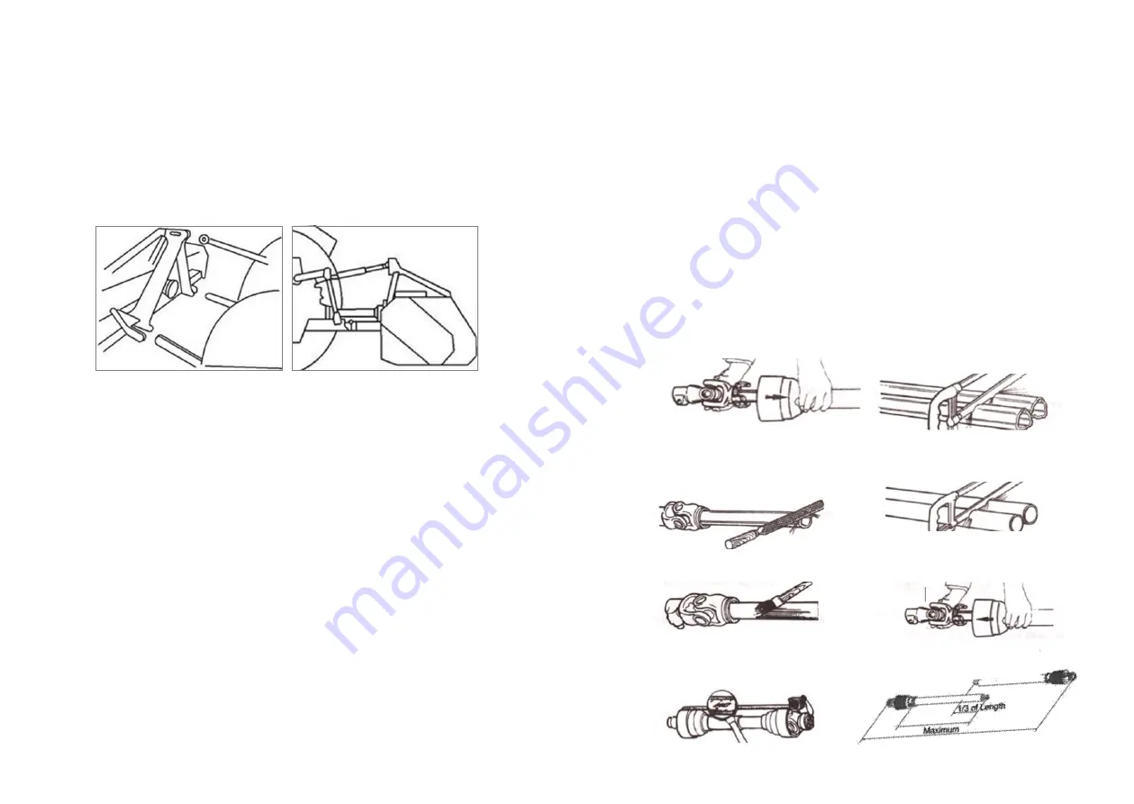
A PTO drive shaft will often need re
-
sizing to fit the tractor. To resize,
attach the mower to the tractor without the PTO drive shaft, raise the
linkage so the PTO drive shaft is level/horizontal. Measure the length
between the tractor
’
s PTO and the PTO drive shaft. If the compressed
(closed) PTO drive shaft length exceeds the one measured in diagram 7
below, then the driveline will need to be cut as per instructions below.
If you are not confident in carrying out this work please contact your local
supplier or mechanic.
1. Remove PTO drive shaft shielding.
2. Cut the driveline tubes to equal
lengths.
3. Use a file to smooth edges of the
driveline tube and clear away all
fillings from the tubes.
4. Cut the guard tubes to the same
length as the driveline tubes.
5. Grease the internal driveline tube.
6. Fit the guard on the shaft.
7. Ensure that the length allows for
at least 16cm (1/3) of overlap


