background image

FSN1962 - 6/2015

English - 29

Submenus for the following signal types:

S-VIDEO, C-VIDEO

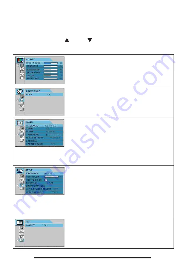
After selecting a main menu category, press the 

+

 button to enter the associated submenus as 

shown below. Next, use the UP 

 and Down

 buttons to navigate to the desired submenu, 

then adjust as needed with the  

+

 and  

-

  buttons. Select the MENU button to exit from the 

submenu or main menu. 

Submenus under the ADJUST menu 

1. BRIGHTNESS  Increases or decreases the brightness. (Range : 0~100)

2. CONTRAST  Increases or decreases the contrast. (Range : 0~100)

3. SHARPNESS  Adjusts the sharpness of video image (Range : 0~100)

4. SATURATION  Changes the tone of color. (Range : 0~100)

5. COLOR  Changes the richness of color. (Range : green 0~50, red 0~50)

6. BACKLIGHT  Adjust backlight dimming level (Range : 0~100)

Submenus under the COLOR TEMP menu 

1. MODE  Changes the color mode. (C1, C2, USER)

2. RED  Red balance. (Only  works with  USER mode)   (Range : 0~100)

3. GREEN  Green balance. (Only  works with  USER mode)   (Range : 0~100)

4. BLUE  Blue balance. (Only  works with  USER mode)   (Range : 0~100)

Submenus under the IMAGE menu 

1. IMAGE SIZE  Changes the image size. (FULL, FILL ASPECT, 1:1, NORMAL)

2. H POSITION  Adjusts the horizontal position of the displayed source image.

(Range : 0~100)

3. V POSITION  Adjusts the vertical position of the displayed source image. 

(Range : 0~100)

4. GAMMA  Adjusts GAMMA value. (VIDEO, BYPASS,1.8,2.0,2.2,2.4,2.6,PACS)

5. FILTER  Sets the sharpness of image. ( Softest, Soft, Normal, Sharp, Sharpest)

6. OVER SCAN  Adjusts the displayed size. (0~8)

7. IMAGE SETTING  Changes the image setting. (Preset 1,2 / User 1,2,3)

8. ZOOM / PAN  Enlarges the image, moves images left and right.

9. FREEZE  Keeps the image still.

Submenus under the SETUP menu 

1. LANGUAGE  Changes the OSD language. (8 languages)

2. OSD COLOR  Adjusts the OSD background from white opaque to translucent. 

3. OSD POSITION  Changes the OSD position. (9 Positions)

4. DURATION  Adjusts the length of time the OSD Menu is present on the screen. 

(5, 10, 20, 30, 60, 90, 120, 180, 240 seconds)

5. RESET SETTINGS  Changes all the OSD values to factory default.

6. AUTO SOURCE SELECT  Disables or enables auto source select. (ON: Searches 

through all possible input sources until an active video source is found.   

OFF: Video input is manually selected.)

7. INACTIVE INPUT  Change the input source between RGBs and YPbPr.

8. PICTURE DELAY  Adjust the picture delay. ( 0: Disable deinteracer engine, 1: 

Enable deinteracer engine)

Submenus under the PIP menu 

1. LAYOUT  Changes the layout. (OFF, PIP, PBP1. PBP2)

2. SOURCE  Changes the secondary source.

3. SIZE  Changes the PIP size. (Small, Large)

4. POSITION  Changes the PIP position.

5. SWAP  Swaps the position of the Primary and Secondary images.

Summary of Contents for FS-L2701D

Page 1: ...Display FS P2601D FS P2601DT FS P2602D FS L2701D FS L2701DT FS S4601D FS S4601DT User s Guide Before connecting operating or adjusting this product please read this instruction booklet carefully and completely ...

Page 2: ...Parts 14 16 Connectors 15 17 Mechanical Drawing 18 Controls 22 On Screen Display OSD 26 Standard Signal Tables 36 Signal Connector Pin Assignments 37 General Specification 40 Cleaning Instructions 45 Fiber Receiver Installation 47 Contacts 48 The specifications and information in this document are subject to change without notice ...

Page 3: ...SN displays Distinct color space settings have been calibrated to well known surgical color preferences providing the user with the ideal surgical visualization system Features include Rapid signal detection robust mode tables Artifact free HD images Fanless sterile field compatible Calibrated to clinical color Image pan zoom freeze picture in picture FSN Medical Technologies has solutions for man...

Page 4: ...r Direct Current lndicates equipotential earth ground Indicates protective earth ground Indicates top bottom direction DC Power control switch Fragile Do not get wet Maximum Stacking Consult the operating instruc tions Indicates the manufacturer Indicates the manufacturing date Authorized representative in the European community Serial Number Humidity limitation Temperature limitation Atmospheric ...

Page 5: ...ved according to the CCC regulations China RoHS labels This symbol indicates that the waste of electronic equipment must not be disposed as unsorted municipal waste and must be collected separately Please contact the manufacturer or other authorized disposal company to decommission your equipment Language English Note A printed copy of the manual in English is provided with the product Users withi...

Page 6: ... or smells coming from it unplug it immediately and contact an authorized dealer or service center 9 Please contact the manufacturer if the set should be installed in an inaccessible area Warning Do not touch input or output connectors and the patient simultaneously Warning This medical LCD monitor is intended for connection to input output signals and other connectors that comply with relevant IE...

Page 7: ...it away from heaters stoves fireplaces and sources of heat 6 Don t place your medical LCD Monitor on an unstable stand Medical LCD monitor may mal function or fall 7 This medical LCD monitor should not topple over when tilted at a 5 angle in any position during NORMAL USE excluding transport 8 In the position specified for transport medical LCD monitor shall not overbalance when tilted at a 10 deg...

Page 8: ...ty Compliance This medical LCD monitor is U L Classified WITH RESPECT TO ELECTRIC SHOCK FIRE AND ME CHANICAL HAZARDS ONLY IN ACCORDANCE WITH UL 60601 1 CAN CSA C22 2 NO 601 1 EEC Safety Compliance This medical LCD monitor unit meets the requirements of EN 60601 1 so as to conform to the Medical Device Directive 93 42 EEC general safety information Use 120V rating 5 15P type plug only in the U S Th...

Page 9: ...o see if agent is compatible Do not allow liquid to enter the display Servicing Do not attempt to service the medical LCD monitor yourself as opening or removing covers may expose you to dangerous voltages or other hazards and will void the warranty Refer all servicing to qualified service personnel Unplug the medical LCD monitor from its power source and refer servicing to qualified personnel und...

Page 10: ...ference 3 Plug the monitor into an outlet on a different electrical circuit than that to which the subject of interference is connected 4 Consult the dealer or an experienced radio TV technician for help NOTICES TO USER This device complies with part 15 of the FCC Rules Operation is subject to the following two conditions 1 this device may not cause harmful interference and 2 this device must acce...

Page 11: ... below The customer or the user of the medical LCD monitor should assure that it is used in such an environment Immunity test IEC 60601 Test level Compliance level Electromagnetic environment guidance Electrostatic discharge ESD IEC 61000 4 2 6 kV contact 8 kV air 6 kV contact 8 kV air Floors should be wood concrete or ceramic tile If floors are covered with synthetic material the relative humidit...

Page 12: ...5 cycle 5 UT 95 dip in UT for 5 sec 5 UT 95 dip in UT for 0 5 cycle 40 UT 60 dip in UT for 5 cycle 70 UT 30 dip in UT for 25 cycle 5 UT 95 dip in UT for 5 sec Main power quality should be that of a typical commercial or hospital environment If the user of monitor requires continued operation during power mains interruptions it is recommended that monitor be powered from an uninterruptible power su...

Page 13: ...ter Separation distance according to frequency of transmitter m 150kHz to 80MHz 80MHz to 800MHz 800MHz to 2 5GHz V1 3Vrms E1 3V m E1 3V m 0 01 0 116 0 116 0 2333 0 1 0 368 0 3687 0 7378 1 1 166 1 1660 0 2333 10 3 687 3 6872 0 7375 100 11 660 11 6600 23 333 For transmitters rated at a maximum output power not listed above the recommended separation dis tance d in meters m can be estimated using the...

Page 14: ...essories User Manual AC DC Adaptor BPM150S24F10 6 23ft 1 9m AC Power Cord 6ft 1 8 m US UK EU China Hospital Grade DVI D Cable 6ft 1 8m BNC Cable 6ft 1 8m D SUB Cable 6ft 1 8m available for purchase S Video Y C Cable 6ft 1 8m available for purchase DC Cable Terminal Male female available for purchase Screw BH M4 USB Cable 6 56ft 2m FS P2601DT ...

Page 15: ...FSN1962 6 2015 English 15 Connectors 26 FS P2601D or FS P2602D Monitor Connector 26 FS P2601DT Monitor Connector ...

Page 16: ...s User Manual AC DC Adaptor BPM150S24F10 6 23ft 1 9m FS L2701DT FS L2701DT AC Power Cord 6ft 1 8 m US UK EU China Hospital Grade DVI D Cable 6ft 1 8m BNC Cable 6ft 1 8m D SUB Cable 6ft 1 8m available for purchase S Video Y C Cable available for purchase DC Cable Terminal Male female available for purchase Screw BH M4 M6 USB Cable 6 56ft 2m FS L2701DT FS S4601DT ...

Page 17: ...FSN1962 6 2015 English 17 Connectors 27 FS L2701D Monitor Connector 46 FS S4601D Monitor Connector 27 FS L2701DT Monitor Connector 46 FS S4601DT Monitor Connector ...

Page 18: ...HOLES OSD membrane switch 74 7 2 94 389 15 31 30 7 1 21 100 3 94 100 3 94 200 7 87 4 M4 x 6 VESA MOUNT HOLES 6 M4 x 10 VESA MOUNT HOLES 100 3 94 200 7 87 cover plate 4 M4 x 6 VESA MOUNT HOLES 6 M4 x 10 VESA MOUN 18 English Mechanical Product Drawing 26 FS P2601D FS P2602D Dimension ...

Page 19: ...tch 4 M4 x 6 VESA MOUNT HOLES 81 7 3 22 389 15 31 37 7 1 21 100 3 94 100 3 94 200 7 87 100 3 94 200 7 87 cover plate 4 M4 x 6 VESA MOUNT HOLES 6 M4 x 10 VESA MOUNT 4 M4 x 6 VESA MOUNT HOLES 6 M4 x 10 VESA MOUNT HOLES English 19 Mechanical Product Drawing 26 FS P2601DT Dimension ...

Page 20: ... 6 2015 648 mm 25 51 in 72 2 83 397 15 63 29 5 1 16 Black masking 72 2 83 397 15 63 29 5 1 16 100 3 94 100 3 94 200 7 87 200 100 cove 20 English Mechanical Product Drawing 27 FS L2701D 27 FS L2701DT Dimension ...

Page 21: ...6 1 32 34 1 1 24 IR sensor Black masking OSD membrane switch 94 3 70 4 1 24 M4 x 20 L max M6 x 30 L max 100 3 94 400 15 75 600 23 62 300 11 81 200 7 87 100 3 94 OSD membrane switch English 21 Mechanical Product Drawing 46 FS S4601D 46 FS S4601DT Dimension ...

Page 22: ...r button however the display unit is still con nected to a power source Note 1 Normal and Off Mode behavior of the Power Indicator Light can be changed according to the requirements of the customer Constant light can be changed to indicate Normal if desired Note 2 The main AC power switch on the dis play s back panel should be in the ON position The front OSD power button is used to turn on the LC...

Page 23: ...tion downward Press to enable PIP Pic ture in Picture function Select from PIP PBP1 PBP2 Press to turn power on off to the display s front LCD screen If this icon is not illumi nated then the power switch on the back of the display has been turned off Press to show the input selection menu and to change the display signal source Input choices DVI 1 DVI 2 SDI VGA RGBS YPbPr S VIDEO C VIDEO QUICK AD...

Page 24: ...pened Pin 4 Connector Ground This is the common ground location Monitor RJ9 Power Management This monitor does not adhere to the VESA DPMS standard when no signal is present on the video input Status LED sign Power Consumption FS P2601D FS L2701D FS P2601DT FS L2701DT FS S4601D FS P2602D no LED sign FS S4601DT Normal mode Off 70W 80W 160W Standby mode Blinking 20W 10W 13 5W OSD power off Constant ...

Page 25: ...ose the OSD menu press the menu button to exit from the main menu or a sub menu 2 Pick a Main Menu Category After entering the OSD use the UP and Down buttons on the front of the display monitor to navigate to a main menu category or The ADJUST menu controls brightness contrast and more The COLOR SETTING menu controls preset or customized color settings The IMAGE menu controls horizontal vertical ...

Page 26: ... 0 100 3 V POSITION Adjusts the vertical position of the displayed source image Range 0 100 4 GAMMA Adjusts GAMMA value VIDEO BYPASS 1 8 2 0 2 2 2 4 2 6 PACS 5 FILTER Sets the sharpness of image Softest Soft Normal Sharp Sharpest 6 OVER SCAN Adjusts the displayed size 0 8 7 IMAGE SETTING Changes the image setting Preset 1 2 User 1 2 3 8 ZOOM PAN Enlarges the image moves images left and right 9 FRE...

Page 27: ...oftest Soft Normal Sharp Sharpest 4 OVER SCAN Adjusts the displayed size 0 8 5 IMAGE SETTING Changes the image setting Preset 1 2 User 1 2 3 6 ZOOM PAN Enlarges the image moves images left and right 7 FREEZE Keeps the image still Submenus under the SETUP menu 1 LANGUAGE Changes the OSD language 8 languages 2 OSD COLOR Adjusts the OSD background from white opaque to translucent 3 OSD POSITION Chang...

Page 28: ...sition of the displayed source image Range 0 100 3 V POSITION Adjusts the vertical position of the displayed source image Range 0 100 4 GAMMA Adjusts GAMMA value VIDEO BYPASS 1 8 2 0 2 2 2 4 2 6 PACS 5 FILTER Sets the sharpness of image Softest Soft Normal Sharp Sharpest 6 OVER SCAN Adjusts the displayed size 0 8 7 IMAGE SETTING Changes the image setting Preset 1 2 User 1 2 3 8 ZOOM PAN Enlarges t...

Page 29: ...ION Adjusts the vertical position of the displayed source image Range 0 100 4 GAMMA Adjusts GAMMA value VIDEO BYPASS 1 8 2 0 2 2 2 4 2 6 PACS 5 FILTER Sets the sharpness of image Softest Soft Normal Sharp Sharpest 6 OVER SCAN Adjusts the displayed size 0 8 7 IMAGE SETTING Changes the image setting Preset 1 2 User 1 2 3 8 ZOOM PAN Enlarges the image moves images left and right 9 FREEZE Keeps the im...

Page 30: ... 0 2 2 2 4 2 6 PACS 3 FILTER Sets the sharpness of image Softest Soft Normal Sharp Sharpest 4 OVER SCAN Adjusts the displayed size 0 8 5 IMAGE SETTING Changes the image setting Preset 1 2 User 1 2 3 6 ZOOM PAN Enlarges the image moves images left and right 7 FREEZE Keeps the image still Submenus under the SETUP menu 1 LANGUAGE Changes the OSD language 8 languages 2 OSD COLOR Adjusts the OSD backgr...

Page 31: ...ting will adjust automatically after auto adjustment When frequency value is wrong picture noise may be present BACKLIGHT Adjust backlight dimming level Setting the backlight too low will causes dark im age and too high will decrease the backlight lifetime AUTO ADJUST Fits to the most appropriate screen on the D SUB Analog signal SHARPNESS Adjusts the sharpness of a video image SATURATION Changes ...

Page 32: ...C D E F G H I J K L M N O P Q R C D E F G H I J K L M N O P Q R C D E F G H I J K L M N O P Q R C D E F G H I J K L M N O P Q R C D E F G H I J K L M N O P Q R C D E F G H I J K L M N O P Q R C D E F G H I J K L M N O P Q R C D E F G H I J K L M N O P Q R C D E F G H I J K L M N O P Q R C D E F G H I J K L M N O P Q R C D E F G H I J K L M N O P Q R A B C D E F G H I J K L M N O P Q R S T U V W A ...

Page 33: ...0 50 100 65 ADJUST BRIGHTNESS CONTRAST CLOCK PHASE BACK LIGHT AUTO ADJUST EXIT DSUB ANALOG MOVE ADJUST 1280X1024 80K x75Hz 50 50 50 100 65 ADJUST BRIGHTNESS CONTRAST CLOCK PHASE BACK LIGHT AUTO ADJUST EXIT DSUB ANALOG MOVE ADJUST 1280X1024 80K x75Hz 50 50 50 100 65 ADJUST BRIGHTNESS CONTRAST CLOCK PHASE BACK LIGHT AUTO ADJUST EXIT DSUB ANALOG MOVE ADJUST 1280X1024 80K x75Hz English 33 On Screen Di...

Page 34: ...cally search for connected input sources Does not affect the sub window when in PIP mode INACTIVE INPUT Change the input source between RGBs and YPbPr PIP LAYOUT Change sub window layout SINGLE PIP PBP1 PBP2 PIP Main Sub window doesn t change aspect ratio PBP1 Main Sub window doesn t change aspect ratio PBP2 Main Sub window H V display 1 1 size PIP SOURCE Selects the PIP source input Change other ...

Page 35: ...een Display OSD System Overview continued Submenu Descriptions Submenu Function Description PIP SWAP Swap main window and sub window contents in PIP PBP1 PBP2 Picture in picture PIP Picture by Picture 1 PBP1 Picture by Picture 2 PBP2 ...

Page 36: ... 879 60 317 40 000 800 x 600 72Hz 48 077 72 188 50 000 800 x 600 75Hz 46 875 75 000 49 500 800 x 600 85Hz 53 674 85 061 56 250 1024 x 768 60Hz 48 363 60 004 65 000 1024 x 768 70Hz 56 476 70 069 75 000 1024 x 768 75Hz 60 023 75 029 78 750 1024 x 768 85Hz 68 677 84 997 94 500 1152 x 864 60Hz 54 348 60 053 80 000 1152 x 864 70Hz 63 955 70 016 94 200 1152 x 864 75Hz 67 500 75 000 108 000 1280 x 720 60...

Page 37: ...nnection 8 No Connection 9 No Connection DC Input Pin No Assignment 1 Ground 2 Ground 3 24V DC 4 F G ground 5 24V DC DVI Input output interface connector Pin No Assignment Pin No Assignment 1 T M D S Data 2 13 No Connection 2 T M D S Data 2 14 5V Power 3 T M D S Data 2 4 Shield 15 GND 4 No Connection 16 Hot Plug Detect 5 No Connection 17 T M D S Data 0 6 DDC Clock 18 T M D S Data 0 7 DDC Data 19 T...

Page 38: ...n No Description 1 SDI input 2 SDI output 3 GND Component RGBS YPbPr interface connector Pin No Description RGBS Description YPbPr 1 RED Pr 2 GREEN Y 3 BLUE Pb 4 H Sync C Sync No Connection 5 V Sync No Connection 6 GND GND C Video interface connector Pin No Description 1 Composite 2 GND S Video interface connector Pin No Description 1 S VIDEO Y Luma 2 S VIDEO C Chroma 3 GND GPIO Pin No Assignment ...

Page 39: ...601D FS S4601DT Pin No Assignment 1 Left positive 2 Left negative 3 Right negative 4 Right positive Headphone input output FS S4601D FS S4601DT Pin No Assignment 1 Line left 2 Line right 3 Ground Equipotential earth terminal This should be connected to other equipment s earth terminal Signal Connector Pin Assignments continued ...

Page 40: ...lling Luminance Typical 450 cd m2 Front Filter Acrylic Anti Reflection coating Power Consumption Maximum 70W Standby Mode 20W Control Key Front Side INPUT PIP MENU POWER Input Signal Video 2 x DVI D 1 x SDI SD HD 3G 1 x VGA 1 x C VIDEO 1 x S VIDEO 1 x Component RGBS YPbPr Output Signal Video 1 x DVI D 1 x SDI SD HD 3G Power Supply AC DC Adaptor AC 100 240V DC 24V 6 25A Mounting Hole VESA standard ...

Page 41: ...alling Luminance Typical 450 cd m2 Front Filter Glass Anti Reflection coating Power Consumption Maximum 70W Standby Mode 20W Control Key Front Side INPUT PIP MENU POWER Input Signal Video 2 x DVI D 1 x SDI SD HD 3G 1 x VGA 1 x C VIDEO 1 x S VIDEO 1 x Component RGBS YPbPr Output Signal Video 1 x DVI D 1 x SDI SD HD 3G Power Supply AC DC Adaptor AC 100 240V DC 24V 6 25A Mounting Hole VESA standard 1...

Page 42: ...alling Luminance Typical 500 cd m2 Front Filter Glass Anti Reflection coating Power Consumption Maximum 70W Standby Mode 20W Control Key Front Side INPUT PIP MENU POWER Input Signal Video 2 x DVI D 1 x SDI SD HD 3G 1 x VGA 1 x C VIDEO 1 x S VIDEO 1 x Component RGBS YPbPr Output Signal Video 1 x DVI D 1 x SDI SD HD 3G Power Supply AC DC Adaptor AC 100 240V DC 24V 6 25A Mounting Hole VESA standard 1...

Page 43: ...ising and falling Luminance Typical 800 cd m2 Touchscreen FS L2701DT USB Projected Capacitive Power Consumption Maximum 80W Standby Mode 10W Control Key Front Side Touch INPUT PIP MENU POWER Input Signal Video 2 x DVI D 1 x SDI SD HD 3G 1 x VGA 1 x C VIDEO 1 x S VIDEO 1 x Component RGBS YPbPr Output Signal Video 1 x DVI D 1 x SDI SD HD 3G Power Supply AC DC Adaptor AC 100 240V DC 24V 6 25A Mountin...

Page 44: ...ng and falling Luminance Typical 650 cd m2 Touchscreen FS S4601DT USB Projected Capacitive Power Consumption Maximum 160W Standby Mode 13 5W Control Key Front Side Touch INPUT PIP MENU POWER Input Signal Video Audio 1 x DVI D 1 x SDI SD HD 3G 1 x VGA 1 x Line in stereo R L Output Signal Video Audio 1 x DVI D 1 x SDI SD HD 3G 1 x Line out stereo R L 1 x Speaker out stereo R L Power Supply Internal ...

Page 45: ...ow your hospital protocol for the handling of blood and body fluids The display is not disinfected or packed in sterile environment Follow your hospital protocol in case the display needs to be disinfected prior to installation Front Filter Proceed as follows 1 Remove dust with a dry lint free non abrasive soft cotton cloth 2 Remove fingerprints or grease using a lint free non abrasive soft cotton...

Page 46: ...prod uct for medical equipment Repeat with water only Wipe dry with a dry cloth The cabinet has been tested for resistance to the following products Virex Ready to use Disinfectant Cleaner Misty Clear Lemon 10 Disinfectant Misty Multi Purpose Disinfectant Cleaner Misty Multi Purpose Disinfectant Cleaner II Zep Heavy duty glass all surface cleaner Klear Screen Screen TFT Kontakt Chemie Incidin Foam...

Page 47: ... DOL bracket with two screws Adding DSP 1 channel SC Insert the DSP receiver into the vacant DVI 2 slot and secure the DSP bracket with two screws Adding DSL 1 channel LC Insert the DSL receiver into the vacant DVI 2 slot and secure the DSL bracket with two screws Brackets for fiber module installation Please place an order to provider to get each bracket for fiber extenders DDL fiber extender DOL...

Page 48: ... Leatherhead Road Chessington Surrey KT9 2NY UK Tel 44 0 208 546 1047 FORESEESON KOREA 404B Pangyoinnovalley B 253 Pangyo ro Bundang gu Seongnam si Gyeonggi do Korea 463 400 Tel 82 31 8018 0780 Fax 82 31 8018 0786 FORESEESON Shanghai Medical Equip Co Ltd Room 307 3F No 56 461 Hongcao Road Caohejing Development District Xuhui Shanghai 200233 Tel 86 21 6113 4188 FORESEESON CUSTOM DISPLAYS INC 2210 E...

Reviews: