background image

5

INSPECTION AND SET-UP

Follow the instructions in the lubrication section of this manual to make sure the chipper 

is greased properly. The initial grease is applied at the factory, but a routine maintenance 

schedule is the user’s responsibility.

Check all bolts and nuts to make sure everything is tight. All hardware is checked at the fac-

tory, but sometimes it will vibrate loose during shipment. Also check all fasteners periodically 

between uses. A wood chipper produces high vibration levels which can cause hardware to 
loosen.

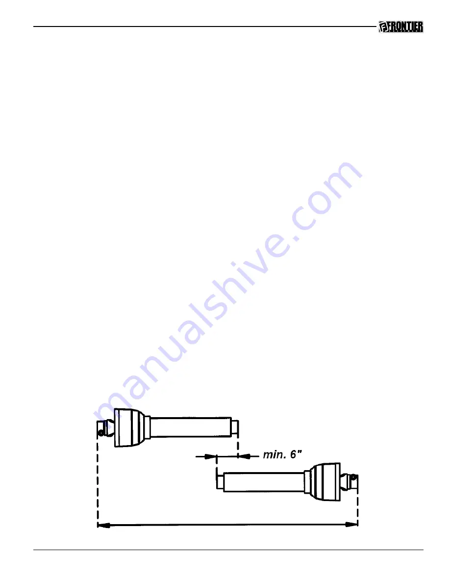
Check the length of the PTO shaft. Some tractor 3-point hitch arms are shorter and require 

a shorter PTO shaft. To determine whether your shaft needs to be cut down to fit you will 

need to connect the 3-point arms to the chipper, connect the PTO shaft to both the tractor 

and chipper, and slowly raise the 3-point hitch. Watch closely to make sure that the PTO 

shaft does not fully retract. If it does, you will need to remove it and cut it down accordingly. 

If the PTO shaft is not fitted properly it can “bottom out” and cause damage to the PTO shaft 

or the chipper. Also check the PTO to make sure the tubes overlap at least 6 in. (15cm) (see 

illustration below) when the chipper is in the operating position. (sitting level on the ground)

Summary of Contents for WC1208

Page 1: ...WOOD CHIPPER O P E R A T O R S M A N U A L WC1208 5PQ990126 05 01 11...

Page 2: ...o we welcome any suggestions or ideas for improvement Please note that it is within our rights to make changes or improvements to our equipment without updating the equipment that was manufactured bef...

Page 3: ...g Tips 6 Chip Chute Adjustments 7 Deflector 7 Feeding Material 8 Maintenance Service 10 BeltTension 10 ReplacingtheBelts 10 Knives 11 Anvil 11 Lubrication 12 Bearings 12 Feed Roller Slide 13 Warranty...

Page 4: ...has been provided inside the front cover of this manual to record the serial number model number purchase date and dealer name Specifications INTRODUCTION Specifications WC1103 WC1105 WC1205 WC1208 C...

Page 5: ...the infeed hopper when loading material into the hopper always load from the side of the hopper This will not allow any part of your body to be pulled into the machine Do not go near any hydraulic lea...

Page 6: ...rovided to insure safe and proper use of the machine and should be heeded at all times If at any time there are damaged and or faded decals contact your dealer for replacements immediately Below is an...

Page 7: ...Check the length of the PTO shaft Some tractor 3 point hitch arms are shorter and require a shorter PTO shaft To determine whether your shaft needs to be cut down to fit you will need to connect the...

Page 8: ...s level Connect the pto shaft to the tractor Be sure that the balls are set in the ball groove of the tractor pto shaft Make sure that the pto safety chains are attached to both the tractor and the ch...

Page 9: ...tion then retighten the set bolt The chute conveniently rotates a full 360 degrees Be sure the set bolt is tight and the chute is locked in place before transporting the chipper Deflector The chip def...

Page 10: ...all twigs and branches the feed roller can slip because of the wet wood or the small size material In this situation it is best to grab the control bar and switch it from forward to reverse several ti...

Page 11: ...splay hours or volts Programming Press and hold O button for three seconds to enter programming mode Press O button momentarily to select parameter to adjust Press and buttons to change setting Only t...

Page 12: ...ese steps to replace the drive belt Figure 10 The WC1208 chipper uses a 5 section banded B 78 belt Remove the belt shield on the left side of the chipper to gain access to the belt Loosen the turnbuck...

Page 13: ...can also be reversed if the edge gets damaged This is a two man job Stop the tractor and remove the PTO and hydraulic connections Remove the access cover on the side of the chipper base and loosen th...

Page 14: ...gs should be greased lightly every 20 hours of use Be sure to wipe all the dirt off of the fitting before greasing Figure 13 Figure 14 Figure 15 Figure 16 Figures 15 16 show the rotor shaft bearings T...

Page 15: ...ese fittings should be greased heavily every 10 hrs of operation and should always be wet with grease Feed Roller Slide The feed roller slide should always be wet with grease Grease the feed slides ev...

Page 16: ...y John Deere according to the terms of the Agricultural Commercial Consumer Equipment Warranty Statement Carefully read the warranty statement on the back of your original purchase order for details o...

Page 17: ...15 NOTES...

Page 18: ...16 Illustrated Parts Breakdowns...

Page 19: ...18 23 Belt 5PQ903497 7 Bolt 9 16 x 2 3 4 5PQ000582 24 Chipper Base 5PQ903400 8 16 5 Groove Pulley 5PQ903039 25 Belt Shield 5PQ903432 9 Key 375 x 2 00 5PQ400857 26 Lock Washer 1 2 5PQ000840 10 1 3 4 SF...

Page 20: ...Nipple 1 8 x 4 5PQ903449 Ref Description Part 16 2 3 8 Flange Bearing 5PQ903024 29 Bolt 1 2 x 1 1 4 5PQ000420 17 Lock Washer 3 4 5PQ000870 30 Lock Washer 1 2 5PQ000840 18 Hex Nut 3 4 5PQ000975 31 Flat...

Page 21: ...ld 5PQ903495 7 Lock Washer 1 4 5PQ000805 8 Nut 1 4 5PQ000900 9 Rubber Block 5PQ505269 10 Bolt 3 8 x 1 1 2 5PQ000280 12 Hydraulic Fitting 5PQ900190 13 Hydraulic Motor 5PQ900178 14 Key 1 4 x 1 5PQ400114...

Page 22: ...eed Tray 5PQ903460 8 Feed Control Spring 5PQ902040 28 Latch Handle 5PQ903455 9 Feed Control Inner Plate 5PQ902038 29 Compression Spring 5PQ505316 10 Feed Control Outer Plate 5PQ902037 30 Flat Washer 1...

Page 23: ...Part 1 Set Bolt 5PQ500148 2 Bolt 3 8 x 1 1 2 5PQ000280 3 Chip Chute 5PQ903486 4 Chip Deflector 5PQ903197 5 Bolt 3 8 x 7 8 5PQ000250 6 Flat Washer 3 8 5PQ001035 7 Locknut 3 8 5PQ003000 8 Clamp Handle...

Page 24: ...105 5 Warning thrown objects 5PQ903106 6 Warning do not place hands 5PQ903100 7 Warning hydraulic pressure 5PQ903114 8 SMV Decal 5PQ903148 9 Decal reverse neutral feed 5PQ903113 10 Decal Red Retrorefl...

Page 25: ...23...

Page 26: ...24...

Page 27: ......

Page 28: ......

Reviews: