background image

22

 Appendix

Bolt Torque & Size Charts (Rev. 3/28/2007)

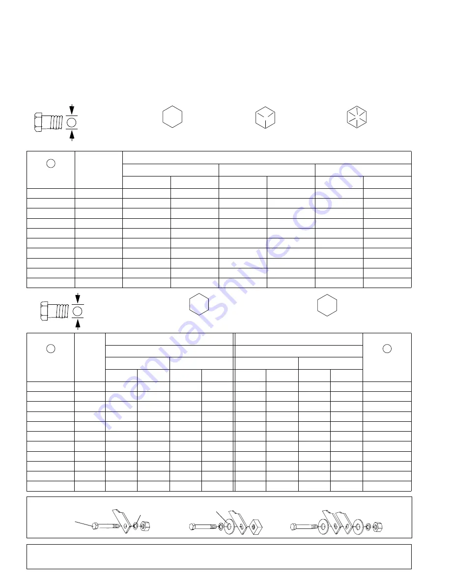
BOLT TORQUE CHART

Always tighten hardware to these values unless a different torque value or tightening procedure is listed for a specific 
application.

Fasteners must always be replaced with the same grade as specified in the manual parts list.

Always use the proper tool for tightening hardware: SAE for SAE hardware and Metric for metric hardware.

Make sure fastener threads are clean and you start thread engagement properly.  

All torque values are given to specifications used on hardware defined by SAE J1701 MAR 99 & J1701M JUL 96.

Diameter 

(Inches)

Wrench

Size

MARKING ON HEAD

SAE 2

SAE 5

SAE 8

lbs-ft

N-m

lbs-ft

N-m

lbs-ft

N-m

1/4"

7/16"

6

8

10

13

14

18

5/16"

1/2"

12

17

19

26

27

37

3/8"

9/16"

23

31

35

47

49

67

7/16"

5/8"

36

48

55

75

78

106

1/2"

3/4"

55

75

85

115

120

163

9/16"

13/16"

78

106

121

164

171

232

5/8"

15/16"

110

149

170

230

240

325

3/4"

1-1/8"

192

261

297

403

420

569

7/8"

1-5/16"

306

416

474

642

669

907

1"

1-1/2"

467

634

722

979

1020

1383

Diameter & 

Thread Pitch 

(Millimeters)

Wrench 

Size

Coarse Thread

Fine Thread

Diameter & 

Thread Pitch 

(Millimeters)

Marking on Head

Marking on Head

Metric 8.8

Metric 10.9

Metric 8.8

Metric 10.9

N-m

lbs-ft

N-m

lbs-ft

N-m

lbs-ft

N-m

lbs-ft

6 x 1.0

10 mm

8

6

11

8

8

6

11

8

6 x 1.0

8 x 1.25

13 mm

20

15

27

20

21

16

29

22

8 x 1.0

10 x 1.5

16 mm

39

29

54

40

41

30

57

42

10 x 1.25

12 x 1.75

18 mm

68

50

94

70

75

55

103

76

12 x 1.25

14 x 2.0

21 mm

109

80

151

111

118

87

163

120

14 x 1.5

16 x 2.0

24 mm

169

125

234

173

181

133

250

184

16 x 1.5

18 x 2.5

27 mm

234

172

323

239

263

194

363

268

18 x 1.5

20 x 2.5

30 mm

330

244

457

337

367

270

507

374

20 x 1.5

22 x 2.5

34 mm

451

332

623

460

495

365

684

505

22 x 1.5

24 x 3.0

36 mm

571

421

790

583

623

459

861

635

24 x 2.0

30 x 3.0

46 mm

1175

867

1626

1199

1258

928

1740

1283

30 x 2.0

A

SAE SERIES 
TORQUE 
CHART

SAE Bolt Head 

Identification

SAE Grade 2

(No Dashes)

SAE Grade 5

(3 Radial Dashes)

SAE Grade 8

(6 Radial Dashes)

A

METRIC SERIES 
TORQUE 
CHART

Metric Bolt Head 

Identification

8.8

Metric

Grade 10.9

10.9

Metric

Grade 8.8

A

A

A

Typical Washer 
Installations

Lock Washer

Flat Washer

8/9/00

Bolt

Summary of Contents for RB1172

Page 1: ...O P E R A T O R S M A N U A L REAR BLADES 5WPMAN0148 Rev 2 16 2009 RB1172 RB1184 RB1196 ...

Page 2: ...ducts it will require cleaning and upkeep Lubricate the unit as specified Observe all safety information in this manual and safety decals on the equipment For service your authorized Frontier dealer has trained mechanics genuine Frontier service parts and the necessary tools and equipment to handle all your needs Use only genuine Frontier service parts Substitute parts will void the warranty and m...

Page 3: ...onditions However through experience and these instructions you should be able to develop procedures suitable to your particular situation The illustrations and data used in this manual were cur rent at the time of printing However due to possible inline production changes your machine may vary slightly in detail We reserve the right to redesign and change the machines as may be necessary without ...

Page 4: ... lbs 256 kg 600 lbs 272 kg Cutting Edge 1 2 x 6 1 2 x 6 1 2 x 6 1 3 x 15 cm 1 3 x 15 cm 1 3 x 15 cm Reversible Reversible Reversible Offset Position Left or Right 4 10 16 4 10 16 4 10 16 10 25 41 cm 10 25 41 cm 10 25 41 cm No of Forward Positions 9 9 9 No of Backfill Positions 9 9 9 No of Tilt Positions 5 5 5 Tractor 3 Point Cat 1 or 2 Cat 1 or 2 Cat 1 or 2 Quick Hitch Optional Cat 1 or 2 Cat 1 or...

Page 5: ...ed with ROPS or ROPS cab and seat belt Keep seat belt securely fastened Falling off power unit can result in death from being run over or crushed Keep foldable ROPS system in locked up position at all times Make sure all safety decals are installed Replace if damaged See Safety Decals section for location A minimum 20 of tractor and equipment weight must be on the tractor front wheels when attachm...

Page 6: ... even when the engine has been turned off Hydraulic system leak down hydraulic system failures mechanical failures or movement of control levers can cause equipment to drop or rotate unexpectedly and cause severe injury or death Service work does not require going under neath Read Operator s Manual for service instruc tions or have service performed by a qualified dealer Always wear relatively tig...

Page 7: ...TH IMPLEMENT CAN RESULT IN SERIOUS INJURY OR DEATH 2 5WP55121 57503 A WARNING BLADE MUST BE PROPERLY SECURED OR IT WILL FALL OFF WHEN ANGLING OR REVERSING Follow all manual instructions and safety rules Lower blade to ground shut off tractor set park brake and remove key Check under center rear of blade to make sure pivot nut and hitch pin are in place as shown in pictorial If pivot nut and pin ar...

Page 8: ... before going between tractor and implement Stand clear of machine while in operation or when it is being raised or lowered FAILURE TO FOLLOW THESE INSTRUCTIONS COULD RESULT IN SERIOUS INJURY OR DEATH WARNING 1002941 A 8 5WP1002941 Safety Decals continued from previous page Unit must not extend more than 4 feet left of center of the tractor when driving on public roads WARNING 1003193 A 7 5WP10031...

Page 9: ...unit or attachment A minimum 20 of tractor and equipment weight must be on the tractor front wheels when attachments are in transport position Without this weight tractor could tip over causing personal injury or death The weight may be attained with a loader front wheel weights ballast in tires or front tractor weights Weigh the tractor and equipment Do not estimate Always wear relatively tight a...

Page 10: ...4 Parking Stand in Storage Position ADJUSTMENTS NEVER GO UNDERNEATH EQUIPMENT Never place any part of the body underneath equipment or between moveable parts even when the engine has been turned off Hydraulic system leak down hydraulic system failures mechanical failures or movement of control levers can cause equipment to drop or rotate unexpectedly and cause severe injury or death Service work d...

Page 11: ...nkage 2 Centering pin Figure 6 Rear Blade Centered Extend the linkage by pulling the center pin 2 and swinging the frame to the desired angle Lock the link age in place by inserting the pin in the desired hole Secure with hair pin clip For offsetting to the left posi tion the linkage on the right side of the frame and extend the linkage Figure 7 Rear Blade Offset Right Blade Pitch The pitch of the...

Page 12: ...degrees from the forward position Reinstall the drop pins and secure The tractor draw bar must be removed or installed in its shortest position to allow the blade to rotate 180 degrees Adjust sway blocks or tighten tractor 3 point sway chains to eliminate implement side to side movement during operation Figure 9 Blade Rotated 180 Degrees NOTES NOTES ...

Page 13: ...and left floating link brackets 14 15 with offset to the inside on each side of the A frame Place sleeve 16 in forward hole and secure assembly into position using two cap screws 18 and lock nuts 19 as shown in Figure 12 NOTE When attaching to tractor install clevis pin 17 into floating links using two 3 4 washers 20 one cot ter pin 21 and hair pin 22 as shown Figure 12 Floating Link Installation ...

Page 14: ... and spacers 5 One washer must be installed between the shoe bracket and the spacers Make sure skid shoe rotates freely to prevent prema ture skid pad wear Figure 14 Skid Shoe Installation END PLATE KIT 5WP1001531 Figure 15 Install one end plate to each end of rear blade using two carriage bolts 4 and flanged lock nuts 5 on each end plate Figure 15 End Plate Installation 1 A Frame assembly 2 Sleev...

Page 15: ... and or front tractor weight to enhance front end stability A minimum 20 of tractor and equipment gross weight must be on front tractor wheels When adding weight to attain 20 of tractor and equipment weight on front tractor wheels you must not exceed the ROPS weight certification Weigh the tractor and equipment Do not estimate ___ Show customer how to make adjustments ___ Present Operator s Manual...

Page 16: ...rts Wear sturdy rough soled work shoes and protective equipment for eyes hair hands hearing and head and respirator or filter mask where appropriate BLADE CUTTING EDGE REPLACEMENT The moldboard blade is reversible and replaceable Remove the cap screws and hex nuts retaining the cut ting edge to the moldboard You may either replace or reverse the cutting edge Secure new or reversed cut ting edge wi...

Page 17: ...148 Rev 5 16 2008 RB1172 RB1184 RB1196 Assembly 18 19 Quick Hitch Bushing Kit Optional 19 Tailwheel Kit Optional 20 Skid Shoe Assembly Optional 21 End Plate Kit Optional 21 PARTS INDEX Rear Blades RB1172 RB1184 RB1196 ...

Page 18: ...18 Parts 5WPMAN0148 Rev 5 16 2008 RB1172 RB1184 RB1196 ASSEMBLY 27 SAFETY DECAL SET 30 COMPLETE DECAL SET ...

Page 19: ...2 Moldboard with decals 20 5WP1026706 1 RB1184 Moldboard with decals 20 5WP1026705 1 RB1196 Moldboard with decals 21 5WP26920 6 7 8 Bolt Plow 5 8 NC x 1 3 4 22 6 7 8 Nut Lock 5 8 NC 23 5WPFA503 1 1 1 Screw HHCS 1 NC x 3 GR8 24 5WPHBL210 1 1 1 Frame Tube Assembly 25 5WP25258 1 Cutting Edge 72 In 12 bolt centers 25 5WP46440 1 Cutting Edge 84 In 12 bolt centers 25 5WP25270 1 Cutting Edge 96 In 12 bol...

Page 20: ...GR5 8 5WP13853 1 Pin Spirol 3 8 x 1 3 4 9 5WP15314 1 Wheel Yoke Assembly 10 1 Screw HHCS 5 8 NC x 7 GR5 11 5WP19025 1 Nut Flange Lock 5 8 NC 12 5WP57182 1 Sleeve 66 x 1 00 x 5 39 13 5WP20879G 1 Tire 4 x 16 Gray 14 5WP29652 1 Link Floating Right 15 5WP29653 1 Link Floating Left 16 5WP7372 1 Sleeve 78 x 1 00 x 2 00 Cat 2 tractor only 17 5WP1591 1 Pin Clevis 75 x 4 38 18 2 Screw HHCS 3 4 NC x 4 1 2 G...

Page 21: ...g located above plate or 4 5WP1005329 1 Bracket Skid Shoe Left 5 5WP52854 6 Sleeve 1 28 x 1 66 x 75 6 5WP27542 2 Pin Klik 7 16 x 2 7 8 Washer Flat 1 1 4 Standard 8 5WP26169 2 Bolt Plow 5 8 NC x 2 1 2 GR5 9 2 Washer Flat 5 8 Standard 10 2 Nut Lock 5 8 NC 11 2 Grease Fitting 1 4 28 Tapered Thread Standard hardware obtain locally END PLATE KIT 5WP1001531 OPTIONAL REF NO PART NO QTY DESCRIPTION 1 1 Mo...

Page 22: ...1 1 2 467 634 722 979 1020 1383 Diameter Thread Pitch Millimeters Wrench Size Coarse Thread Fine Thread Diameter Thread Pitch Millimeters Marking on Head Marking on Head Metric 8 8 Metric 10 9 Metric 8 8 Metric 10 9 N m lbs ft N m lbs ft N m lbs ft N m lbs ft 6 x 1 0 10 mm 8 6 11 8 8 6 11 8 6 x 1 0 8 x 1 25 13 mm 20 15 27 20 21 16 29 22 8 x 1 0 10 x 1 5 16 mm 39 29 54 40 41 30 57 42 10 x 1 25 12 x...

Page 23: ...c HHCS Hex Head Cap Screw HT Heat Treated JIC Joint Industry Council 37 Degree Flare LH Left Hand LT Left m Meter mm Millimeter M Male MPa Mega Pascal N Newton NC National Coarse NF National Fine NPSM National Pipe Straight Mechanical NPT National Pipe Tapered NPT SWF National Pipe Tapered Swivel Female ORBM O Ring Boss Male P Pitch PBY Power Beyond psi Pounds per Square Inch PTO Power Take Off QD...

Page 24: ...e trademarks of Woods Equipment Company Frontier Equipment and the Frontier logo are trademarks of Deere Company All other trademarks trade names or service marks that appear in this man ual are the property of their respective companies or mark holders Specifications subject to change without notice ...

Reviews: