Operating
instructions
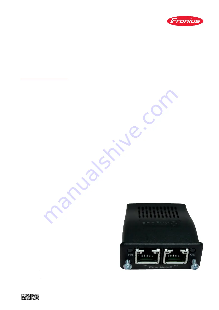
RI FB PRO/iRI MOD/i CC Ethernet/IP-2P
42,0410,2198
015-02052022
DE
Bedienungsanleitung
EN-US
Operating instructions
Page 1: ...Operating instructions RI FB PRO i RI MOD i CC Ethernet IP 2P 42 0410 2198 015 02052022 DE Bedienungsanleitung EN US Operating instructions...
Page 2: ......
Page 3: ...ypen 9 Verf gbarkeit der Eingangssignale 9 Eingangssignale vom Roboter zur Stromquelle 9 Wertebereich Working mode 14 Wertebereich Documentation mode 14 Wertebereich Process controlled correction 15 W...
Page 4: ...n dieses Ger tes und aller Systemkomponenten lesen und verstehen Anschl sse und Anzeigen 1 2 3 4 5 6 7 8 Pin Belegung RJ 45 ProfiNet Anschluss 1 TX 2 TX 3 RX 6 RX 4 5 7 8 Normalerweise nicht ver wende...
Page 5: ...ung f r die Pla nung und Installation vonEtherNet IP Systemen zu beachten Seitens Hersteller wurden die EMV Tests mit dem Kabel IE C5ES8VG0030 M40M40 F durchgef hrt bertragungs Geschwindigkeit 10 Mbit...
Page 6: ...e Input Da ta Stan dard Data from power source to robot 100 40 Con suming Instance Output Data Standard Data from robot to power source 150 40 Economy Image Produ cing In stance Input Da ta Stan dard...
Page 7: ...halter im Interface DIP Schalter 8 7 6 5 4 3 2 1 IP Adresse OFF OFF OFF OFF OFF ON 1 OFF OFF OFF OFF ON OFF 2 OFF OFF OFF OFF ON ON 3 ON ON ON ON ON OFF 62 ON ON ON ON ON ON 63 Anleitung f r das Einst...
Page 8: ...us Konfiguration die gew nschte IP Adresse f r das Inter face eingeben Beispielsweise 192 168 0 12 10 Konfiguration setzen ausw hlen 11 Feldbus Modul neu starten ausw hlen die eingestellte IP Adresse...
Page 9: ...7 Umrechnungsbeispiele f r positiven Wert SINT16 z B gew nschter Drahtvorschub x Faktor 12 3 m min x 100 1230dez 04CEhex f r negativen Wert SINT16 z B gew nschte Lichtbogen Korrektur x Faktor 6 4 x 10...
Page 10: ...t 4 High 7 7 1 0 8 Gas on steigend 1 9 Wire forward steigend 2 10 Wire backward steigend 3 11 Error quit steigend 4 12 Touch sensing High 5 13 Torch blow out steigend 6 14 Processline selection Bit 0...
Page 11: ...2 4 0 32 TWIN mode Bit 0 High Siehe Tabelle Wertebereich TWIN mode auf Seite 15 1 33 TWIN mode Bit 1 High 2 34 3 35 4 36 5 37 Documentation mode High Siehe Tabelle Wertebereich Do cumentation mo de a...
Page 12: ...60 ExtInput5 OPT_Output 5 High 5 61 ExtInput6 OPT_Output 6 High 6 62 ExtInput7 OPT_Output 7 High 7 63 ExtInput8 OPT_Output 8 High 4 8 0 7 64 71 Welding characteristic Job number UINT16 0 bis 1000 1 9...
Page 13: ...im Schwei verfahren ConstantWire Hotwire current UINT16 0 0 bis 6553 5 A 10 7 14 15 0 7 112 127 Beim Schwei verfahren MIG MAG Puls Synergic MIG MAG Standard Syn ergic MIG MAG PMC MIG MAG LSC CMT Pulse...
Page 14: ...33 0 7 264 271 17 34 0 7 272 279 35 0 7 280 287 18 36 0 7 288 295 37 0 7 296 303 19 38 0 7 304 311 Seam number UINT16 0 bis 65535 1 39 0 7 312 319 Wertebereich Working mode Bit 4 Bit 3 Bit 2 Bit 1 Bi...
Page 15: ...0 Volt 10 Wertebereich prozessabh ngige Korrektur Wertebereich Processline selection Bit 1 Bit 0 Beschreibung 0 0 Prozesslinie 1 default 0 1 Prozesslinie 2 1 0 Prozesslinie 3 1 1 Reserviert Wertebere...
Page 16: ...0 0 0 0 Heartbeat Powersource High Low 1 Hz 1 1 Power source ready High 2 2 Warning High 3 3 Process active High 4 4 Current flow High 5 5 Arc stable touch signal High 6 6 Main current signal High 7 7...
Page 17: ...ply status Low 7 23 3 0 24 Sensor status 1 High Siehe Tabelle Zu ordnung Sensorsta tus 1 4 auf Seite 19 1 25 Sensor status 2 High 2 26 Sensor status 3 High 3 27 Sensor status 4 High 4 28 5 29 6 30 7 3...
Page 18: ...Output3 OPT_In put3 High 3 59 ExtOutput4 OPT_In put4 High 4 60 ExtOutput5 OPT_In put5 High 5 61 ExtOutput6 OPT_In put6 High 6 62 ExtOutput7 OPT_In put7 High 7 63 ExtOutput8 OPT_In put8 High 4 8 0 7 64...
Page 19: ...216 223 14 28 0 7 224 231 29 0 7 232 239 15 30 0 7 240 247 31 0 7 248 255 16 32 0 7 256 263 Wire position SINT16 327 68 bis 327 67 mm 100 33 0 7 264 271 17 34 0 7 272 279 35 0 7 280 287 18 36 0 7 288...
Page 20: ...it 1 Bit 0 Beschreibung 0 0 0 0 0 kein Prozess oder Parameteranwahl intern 0 0 0 0 1 MIG MAG Puls Synerigc 0 0 0 1 0 MIG MAG Standard Synergic 0 0 0 1 1 MIG MAG PMC 0 0 1 0 0 MIG MAG LSC 0 0 1 0 1 MIG...
Page 21: ...lability of Input Signals 27 Input Signals From Robot to Power Source 27 Value Range for Working Mode 33 Value Range for Documentation Mode 33 Value range for Process controlled correction 34 Value ra...
Page 22: ...rules and user documentation for this equip ment and all system components Connections and Displays 1 2 3 4 5 6 7 8 RJ45 connection 1 TX 2 TX 3 RX 6 RX 4 5 7 8 Not normally used to ensu re signal com...
Page 23: ...y the manufacturer with the cable IE C5ES8VG0030M40M40 F Transmission speed 10 Mbit s or 100 Mbit s Bus connection RJ 45 Ethernet M12 Configuration Parameters In some robot control systems it may be n...
Page 24: ...er Size Byt e Con suming Instance Output Data Standard Data from robot to power source 150 40 Economy Image Produ cing In stance Input Da ta Stan dard Data from power source to robot 101 16 Con suming...
Page 25: ...e interface Dip switch 8 7 6 5 4 3 2 1 IP address OFF OFF OFF OFF OFF ON 1 OFF OFF OFF OFF ON OFF 2 OFF OFF OFF OFF ON ON 3 ON ON ON ON ON OFF 62 ON ON ON ON ON ON 63 Instructions for setting the IP a...
Page 26: ...9 Enter the desired IP address for the interface under Module configuration For example 192 168 0 12 10 Select Set configuration 11 Select Restart module The set IP address is applied 26...
Page 27: ...ge from 32768 to 32767 Conversion examples for a positive value SINT16 e g desired wire speed x factor 12 3 m min x 100 1230dec 04CEhex for a negative value SINT16 e g arc correction x factor 6 4 x 10...
Page 28: ...on page 33 3 3 Working mode Bit 1 High 4 4 Working mode Bit 2 High 5 5 Working mode Bit 3 High 6 6 Working mode Bit 4 High 7 7 1 0 8 Gas on Increa sing 1 9 Wire forward Increa sing 2 10 Wire backward...
Page 29: ...rd Economy WORD BYTE BIT BIT 1 2 0 16 Welding Simulation High 1 17 Synchro pulse on High 2 18 3 19 4 20 5 21 6 22 Wire brake on High 7 23 Torchbody Xchange High 3 0 24 1 25 Teach mode High 2 26 3 27 4...
Page 30: ...T BIT 2 4 0 32 TWIN mode Bit 0 High See table Value Range for TWIN Mode on page 34 1 33 TWIN mode Bit 1 High 2 34 3 35 4 36 5 37 Documentation mode High See table Value Range for Docu mentation Mode o...
Page 31: ...xtInput5 OPT_Output 5 High 5 61 ExtInput6 OPT_Output 6 High 6 62 ExtInput7 OPT_Output 7 High 7 63 ExtInput8 OPT_Output 8 High 4 8 0 7 64 71 Welding characteristic Job number UINT16 0 to 1000 1 9 0 7 7...
Page 32: ...ing process ConstantWire Hotwire current UINT16 0 0 to 6553 5 A 10 7 14 15 0 7 112 127 With the welding process MIG MAG pulse synergic MIG MAG standard syner gic MIG MAG PMC MIG MAG LSC CMT Pulse dyna...
Page 33: ...272 279 35 0 7 280 287 18 36 0 7 288 295 37 0 7 296 303 19 38 0 7 304 311 Seam number UINT16 0 to 65535 1 39 0 7 312 319 Value Range for Working Mode Bit 4 Bit 3 Bit 2 Bit 1 Bit 0 Description 0 0 0 0...
Page 34: ...Volts 10 Value range for process dependent correction Value range Pro cess line selec tion Bit 1 Bit 0 Description 0 0 Process line 1 default 0 1 Process line 2 1 0 Process line 3 1 1 Reserved Value...
Page 35: ...tbeat Powersource High Low 1 Hz 1 1 Power source ready High 2 2 Warning High 3 3 Process active High 4 4 Current flow High 5 5 Arc stable touch signal High 6 6 Main current signal High 7 7 Touch signa...
Page 36: ...n supply status Low 7 23 3 0 24 Sensor status 1 High See table Assign ment of Sensor Sta tuses 1 4 on page 38 1 25 Sensor status 2 High 2 26 Sensor status 3 High 3 27 Sensor status 4 High 4 28 5 29 6...
Page 37: ...tput3 OPT_In put3 High 3 59 ExtOutput4 OPT_In put4 High 4 60 ExtOutput5 OPT_In put5 High 5 61 ExtOutput6 OPT_In put6 High 6 62 ExtOutput7 OPT_In put7 High 7 63 ExtOutput8 OPT_In put8 High 4 8 0 7 64 7...
Page 38: ...0 7 224 231 29 0 7 232 239 15 30 0 7 240 247 31 0 7 248 255 16 32 0 7 256 263 Wire position SINT16 327 68 to 327 67 mm 100 33 0 7 264 271 17 34 0 7 272 279 35 0 7 280 287 18 36 0 7 288 295 37 0 7 296...
Page 39: ...0 0 No internal parameter selection or process 0 0 0 0 1 MIG MAG pulse synergic 0 0 0 1 0 MIG MAG standard synergic 0 0 0 1 1 MIG MAG PMC 0 0 1 0 0 MIG MAG LSC 0 0 1 0 1 MIG MAG standard manual 0 0 1...
Page 40: ......