


147
EN
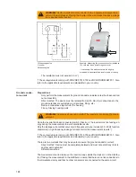
All the inputs (terminals) on the inverter must be measured individually.
One point is sufficient on the wall bracket, as the terminals are interconnected internally.
Capacitor discharge time is at least 6 minutes.
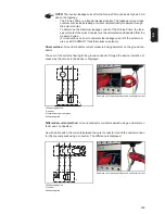
Ground conduc-
tor resistance
-
Only perform the measurement if the insulation resistance test produced an accept-
able result.
-
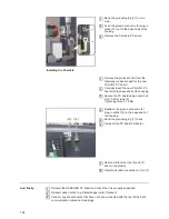
Fit the cover back onto the inverter.
-
Correct functioning of the ground conductor is only guaranteed if the results of the
measurement between the cover and the wall bracket are acceptable.
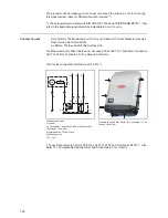
-
The device being tested must be safely isolated from the AC grid (the grid lead [L, N]
must not be connected). If the AC grid cannot be disconnected from the wall bracket,
the relevant safety precautions must be taken.
-
Place the inverter back in the wall bracket.
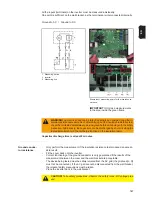
Ground to AC / Ground to DC
1 Measuring device
2 Inverter
9 Measuring line
Examples of measuring points for the insulation re-
sistance
IMPORTANT!
Only take measurements
in the area inside the green frame.
WARNING!
An electric shock can be fatal. Capacitors can charge during the in-
sulation resistance measurement. After carrying out the insulation resistance test,
check that all tested potentials are de-energised before continuing with the safety
inspection. Alternatively, the capacitors can be discharged by short-circuiting the
tested potentials or via the discharge function on the insulation tester.
CAUTION!
Take safety precautions. Observe the safety rules - DC voltage pres-
ent!
Summary of Contents for Primo 3.0-1
Page 2: ...2 ...
Page 5: ...Allgemeine Informationen ...
Page 6: ......
Page 13: ...Fehler Suchhilfe ...
Page 14: ......
Page 32: ...32 ...
Page 33: ...Komponenten austauschen ...
Page 34: ......
Page 54: ...54 DC Trenner auf ON stellen 6 ...
Page 65: ...Sicherheitstechnische Überprüfung ...
Page 66: ......
Page 78: ...78 ...
Page 81: ...General information ...
Page 82: ......
Page 89: ...Error location aid ...
Page 90: ......
Page 108: ...108 ...
Page 109: ...Changing components ...
Page 110: ......
Page 130: ...130 Set the DC disconnector to ON 6 ...
Page 141: ...Safety Inspections ...
Page 142: ......
Page 154: ...154 ...
Page 155: ...Appendix ...
Page 158: ...158 ...
Page 159: ...159 ...