


43
EN-US
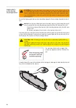
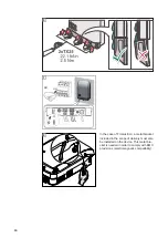
Closing the Device:
Symo 10-20 / US, Eco / 15.0
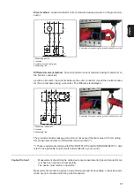
Check the correct position of the 11
EMC springs – the EMC springs are
held in place by small indentations
(The overvoltage PC board may be located
in the marked area (5))
Position the power stage set lid and fit
it with six screws 5x16 TX25 (4)
[3
Nm]
, attach EMC bracket
Attach the inverter at the top and allow
it to engage with the mounting bracket
Using 2 screws 5x25 TX25 (3), fix to
the mounting bracket securely
[2.5
Nm]
If applicable, mount all plug connecti-
onsmounting bracket
Mount Datcom lid with 4 screws 5x25
TX25 (2)
[2.5 Nm]
Set the DC disconnector (1) to the I po-
sition
(5)
NOTE!
To ensure a sufficient
EMC connection is established, all
EMC springs must be present
1
(4)
(4)
(4)
(4)
(4)
(4)
NOTE!
To avoid damage to the
base shell, the inverter must not
exceed an angle of 11°.
2
3
(3)
(3)
3
4
(1)
(2)
(2)
NOTE!
See section "Clip the in-
verter onto the mounting bracket"
6
7
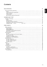
Summary of Contents for Eco 15.0-3-208 US
Page 2: ...2...
Page 4: ...4...
Page 5: ...Allgemeine Informationen...
Page 6: ......
Page 8: ...8 Mess und Pr f mittel Digitales Multimeter Equipment f r die sicherheitstechnische berpr fung...
Page 9: ...Einbau State 112 KIT...
Page 10: ......
Page 15: ...15 DE 1 2 3 4 5 1 2 3 4 22 1 lbf in 2 5 Nm 5...
Page 19: ...Sicherheitstechnische berpr fung...
Page 20: ......
Page 32: ...32...
Page 34: ...34...
Page 35: ...General Information...
Page 36: ......
Page 38: ...38 Measuring and In spection Equip ment Digital multimeter Equipment for safety inspection...
Page 39: ...Installation State 112 KIT...
Page 40: ......
Page 45: ...45 EN US 1 2 3 4 5 1 2 3 4 22 1 lbf in 2 5 Nm 5...
Page 49: ...Safety inspection...
Page 50: ......
Page 62: ...62...
Page 63: ...63 EN US...


