background image

1.

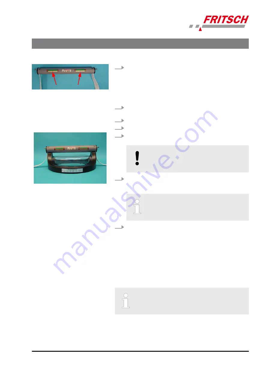
The starting position of the clamping system is the position at

which both indicators are roughly in the centre of the respective

display range.
This position later ensures that sieve stacks of various heights can

be clamped easily, or that there is sufficient space to release the

system, remove it from the sieve stack and place it behind the

device.

2.

Insert the toothed belt in the belt clamping device as described in

Ä

 Chapter 7.2.1.2 ‘Fitting and clamping the sieves’ on page 26.

3.

Insert the sieve set and pour in the sieving stock.

4.

Fit the TorqueMaster clamping lid.

5.

Place the clamping unit on the clamping lid. The clamping unit

must be fitted as centrally as possible.

NOTICE!
This symmetry is ensured by correctly adjusting and

securing the toothed belt.

6.

Lightly tighten the toothed belts on both sides and move the

clamping lever upwards, as described in 

Ä

 Chapter 7.2.1.2 ‘Fitting

and clamping the sieves’ on page 26 under point 9.

Make sure that both indicators remain in their central

position.

7.

The clamping system can now be clamped using the cordless

screwdriver.

7.2.7.2 

Clamping the TorqueMaster

Clamping with a cordless screwdriver until it disengages applies a repro-

ducible force of ~ 1 kN to the sieve cover.
Clamping processes during which the friction clutch of the cordless

screwdriver does not disengage (e.g. due to defect, dead battery or

operating error) do not provide the desired clamping force.

The correct clamping force is only achieved if the friction

clutch of the cordless screwdriver triggers during the

clamping process.


Accessories


- 35 -


Summary of Contents for PULVERISETTE 0

Page 1: ...VIBRATORY MICRO MILL PULVERISETTE 0 Operating instructions Valid starting with 00 6020 215 Read the instructions prior to performing any task Translation of the original operating instructions ...

Page 2: ...Version 12 2014 Index 006 Fritsch GmbH Milling and Sizing Industriestraße 8 D 55743 Idar Oberstein Telephone 49 0 6784 70 0 Fax 49 0 6784 70 11 email info fritsch de Internet www fritsch de ...

Page 3: ...meinschaft e V An audit certified that Fritsch GmbH conforms to the requirements of the DIN EN ISO 9001 2008 The enclosed Conformity Declaration lists the guidelines the FRITSCH instrument conforms to to be able to bear the CE mark Certification CE Conformity Certifications and CE conformity 3 ...

Page 4: ...ainst restart 14 2 8 3 Overload protection 15 3 Technical data 16 3 1 Dimensions 16 3 2 Weight 16 3 3 Operating noise 16 3 4 Voltage 16 3 5 Current consumption 16 3 6 Power consumption 16 3 7 Electrical fuses 17 3 8 Load 17 3 9 Material 17 3 10 Final fineness of a grinding process with the PULVERI SETTE 0 17 4 Installation 18 4 1 Transport 18 4 2 Unpacking 18 4 3 Setting up 18 4 4 Ambient conditio...

Page 5: ...ing parameters 30 7 2 3 2 Wetting agents 30 7 2 3 3 Feeding the rinsing liquid 31 7 2 3 4 Extracting the passing particles 31 7 2 3 5 Tips for wet sieving of difficult sieving stock 32 7 2 4 Cleaning the test sieves mesh wire sieves 32 7 2 5 Setting the sieving time 33 7 2 6 Einstellung und Anzeige der Amplitude 33 7 2 7 TorqueMaster for easy clamping of the sieve set 34 7 2 7 1 Fitting the Torque...

Page 6: ...13 Exclusion of liability 46 14 Safety logbook 48 15 Index 50 Table of contents 6 ...

Page 7: ...xcept that the ANALYSETTE 3 SPARTAN like the PRO version also uses a sieve set 1 Lid also used in the ANALYSETTE 3 as a clamping lid for the 100 mm test sieves 2 Mortar with grinding ball 3 Vibratory plate 4 Knurled knob 5 Toothed belt 6 Belt clamping device 7 Control panel Basic structure 7 ...

Page 8: ...elines and operating conditions are authorised by those responsible for the safety of the machine to carry out the required work and are able to recognize and avoid possible hazards as defined for skilled workers in IEC 364 In order to prevent hazards to users follow the instructions in this manual Malfunctions that impair the safety of persons the of the PULVERISETTE 0 or other material property ...

Page 9: ...efore continuous operation is pos sible without heating the sample material and the overall mill system The mortar bowl with 50 mm diameter grinding ball or 70 mm for agate only and grinding stock oscillates vertically This causes the grinding ball in the mortar bowl to vibrate and comminute the grinding stock by impact and friction 2 2 2 Amplitude control An electronic control circuit guides the ...

Page 10: ...ion of the installation can result in property damage and thus endanger per sons Therefore we assume absolutely no responsibility or liability for loss damage or costs that result from errors at installation improper operation or improper use or improper maintenance or are in any way connected to these The applicable accident prevention guidelines must be complied with Generally applicable legal a...

Page 11: ...ll result in serious or fatal injury DANGER This symbol and keyword combination designates contents and instructions for proper use of the machine in explosive areas or with explosive substances Ignoring information with this designation will result in serious or fatal injury DANGER This symbol and keyword combination designates contents and instructions for proper use of the machine with com bust...

Page 12: ... used Example 1 Loosen screw 2 CAUTION Risk of entrapment at the lid Close the lid carefully 3 Tighten screw This symbol emphasises useful tips and recommendations as wells as information for efficient operation without mal function To emphasise procedure instructions results lists references and other elements the following designations are used in this manual Designation Explanation 1 2 3 Step b...

Page 13: ...rn to prevent hearing damage WARNING The maximum accepted concentration MAC levels of the relevant safety guidelines must be observed if necessary ventilation must be provided or the machine must be oper ated under an extractor hood DANGER Explosion hazard When grinding oxidizable substances e g metals or coal there is a risk of spontaneous combustion dust explosion if the share of fine particles ...

Page 14: ...tive equipment is to be used as intended and may not be disabled or removed All protective equipment is to be regularly checked for integrity and proper functioning NOTICE The toothed belts must only be released or clamped in the switched off state Before switching on again ensure that the two toothed belts are evenly tightly clamped using the knurled knobs 2 7 Hazardous points n Crushing hazard a...

Page 15: ...2 8 3 Overload protection The mains fuse provides overload protection Safety information and use 15 ...

Page 16: ...ise is greatly reduced by using the sound absorption hood made of plexiglas order no 00 0130 17 3 4 Voltage The device can be operated in two voltage ranges n Single phase alternating current 115V 10 and n Single phase alternating current 230 V 10 See also Ä Chapter 4 5 Electrical connection on page 19 It is not necessary to change the voltage range manually 3 5 Current consumption Depending on th...

Page 17: ...of the PULVERISETTE 0 is up to 6 kg 3 9 Material n Maximum feed size 5 mm n Maximum feed quantity 10 ml 3 10 Final fineness of a grinding process with the PULVERISETTE 0 The achievable final fineness PULVERISETTE 0 of the grinding stock is approx 10 µm Depending on the grindability of the sample and the grinding duration Technical data 17 ...

Page 18: ...den plate must be unscrewed n Compare the contents of the delivery with your order Keep the wooden plate screws and washers as this trans port securing device must be reattached in the case of fur ther transport or return 4 3 Setting up n Place the device on a flat stable surface It does not have to be fas tened to the surface Leave sufficient space beside the device for placing the accessories us...

Page 19: ...elative humidity at 40 C n The room temperature has to stay between 5 40 C n Altitudes up to 2000 m n Degree of pollution 2 according to IEC 664 4 5 Electrical connection Before establishing the connection compare the voltage and current values stated on the type plate with the values of the mains system to be used CAUTION Ignoring the values on the type plate may result in damage to the electrica...

Page 20: ...d releases us from liability for any resulting damage to the device 1 Switch main switch to 0 2 Switch the device on at the main switch while holding down the Stop key The device is now in Setup mode 3 The Sieving Time display now shows the default setting 04 for 230 V 06 for 115 V The value 07 is preset for a mains voltage of 100 V in Japan 4 These values can be changed with the Sieving Time key ...

Page 21: ...n the control panel lights up n The display shows the default setting 5 2 Function check n Fill the mortar 2 with 5 10 ml of sand insert the grinding ball and clamp the lid 1 n Set the amplitude to 2 mm See Ä Chapter 6 3 Setting the ampli tude on page 25 n When everything is correctly clamped start the function check with START Whether the set amplitude has been reached can be checked on the displ...

Page 22: ...rinding stock 5 Put on the clamping lid 6 Attach the knurled knob to the lid 7 Lightly pull the toothed belt tight and move it upwards until its teeth interlock with the teeth of the belt clamping device 8 Move the clamping lever upwards Make sure that the teeth of the toothed belt interlock with the teeth of the belt clamping device 9 By turning the knurled knobs to the right tighten the mortar e...

Page 23: ...in suspension CAUTION Do not allow any liquids to flow into the device To reduce the grinding noise we recommend using a sound absorption hood order no 00 0130 17 6 1 3 Grinding with liquid nitrogen CAUTION Only use grinding vessels and grinding balls made of stain less steel tungsten carbide or zirconium oxide for grinding with liquid nitrogen The device for grinding in liquid nitrogen no 00 2000...

Page 24: ... is facing backwards and the amplitude display 7 is facing forwards The device is then clamped like a normal sieve set Liquid nitrogen is then poured in carefully through the funnel 6 it evap orates immediately and escapes through the bent ventilation tube The boiling nitrogen can be observed through the transparent Makrolon screen Nitrogen is added until the amount of vapour escaping decreases Th...

Page 25: ...0 NOTICE Grinding at an amplitude higher than 2 mm can cause damage to the device and the grinding set 6 3 1 Displaying the amplitude The amplitude must be checked on the amplitude plate on the clamping lid The lines that appear to touch one another display the set amplitude The principle is based on the persistence of vision of the human eye Example for 2 mm amplitude Using the device 25 ...

Page 26: ...and sieve pans can be clamped with different diame ters and heights 7 2 1 Conducting a sieve analysis 7 2 1 1 Sieve mesh widths that can be used n Dry sieving 100 µm to 25 mm without sieving aids 32 µm to 25 mm with sieving aids n Wet sieving 20 µm or greater n Micro sieving PRO version only 5 µm to 100 µm 7 2 1 2 Fitting and clamping the sieves On the vibratory plate it is possible to fit up to 1...

Page 27: ...mping device downwards and insert the toothed belt through the holder from the inside to the outside The teeth of the toothed belt interlock with the teeth of the belt clamping device 4 Place the sieve set with the sieve pan centrally on the rubber pad of the vibratory plate 5 Place the sieving stock into the top sieve 6 Fit the clamping lid so that the inner rubber surface seals the sieve edge 7 ...

Page 28: ...on the sieve cover Remove the knurled knobs with tension belt fitting from the clamping lid and place them beside the machine Take down the sieve set completely and weigh it 7 2 1 3 Multiple sieving Due to the special shape of the intermediate sieve pan two or three sievings two or three sieve sets on top of each other can be carried out in a single step Setup example Sieve pan with 2 sieves and s...

Page 29: ...eve an amplitude set point of 3 mm In this case the sieve shaker controller can no longer set the optimal working point the sieve shaker vibrates with a lower amplitude and fre quency The amplitude set point must be reduced accordingly in this case When the machine has warmed up the set point can be increased accordingly 7 2 2 2 Sieving aids To shorten the sieving time sieving aids can be attached...

Page 30: ...the top sieve and clamp the wet clamping lid CAUTION Do not allow any liquids to flow into the device 7 2 3 1 Sieving parameters Parameters Average High percentage of fine ground material Sieving time 3 10 min approx 15 min Amplitude 2 2 5 mm 7 2 3 2 Wetting agents Wetting agents improve dispersion n Add tensides in liquid form washing up liquid Dusazin etc in small amounts only dropwise to preven...

Page 31: ...ble damage to the sieve mesh wire If there is a backup in the sieve set we recommend reducing the sample quantity switching on the Interval mode or using the intermediate sieve ring see Ä Chapter 7 2 3 5 Tips for wet sieving of difficult sieving stock on page 32 Make sure that the small opening O in the wet clamping lid is open only then does it prevent overpressure from developing and possible da...

Page 32: ...he hose system additional liquid is sprayed in through three nozzles and thus counteracts a possible backup These nozzles are arranged so that the lower as well as the upper sieve surfaces are sprayed This arrangement also circulates the sieving stock If necessary a further intermediate sieve ring can also be mounted above a sieve that is prone to backup 7 2 4 Cleaning the test sieves mesh wire si...

Page 33: ...1 hour let the device cool down Continuous operation is set by holding down the key until P or 00 appears on the display 7 2 6 Einstellung und Anzeige der Amplitude This is done in the same way for sieving as for grinding with the mortar attachment see Ä Chapter 6 3 Setting the amplitude on page 25 and Ä Chapter 6 3 1 Displaying the amplitude on page 25 Accessories 33 ...

Page 34: ...amping aid included is to be used exclusively for releasing a clamped sieve stack in case of malfunction of the cordless screwdriver The unclamping aid has no torque limitation and if it is used for clamping prevention of operating errors and possible irreparable damage to the clamping unit can therefore not be guaranteed 7 2 7 1 Fitting the TorqueMaster clamping device The sieves are fitted as de...

Page 35: ...ICE This symmetry is ensured by correctly adjusting and securing the toothed belt 6 Lightly tighten the toothed belts on both sides and move the clamping lever upwards as described in Ä Chapter 7 2 1 2 Fitting and clamping the sieves on page 26 under point 9 Make sure that both indicators remain in their central position 7 The clamping system can now be clamped using the cordless screwdriver 7 2 7...

Page 36: ...irreparable damage to the clamping system for which no liability can be assumed The use of cordless screwdrivers that merely have a lower torque will result in the sieve stack being clamped with an insufficient clamping force CAUTION Follow the separate operating instructions of the cordless screwdriver manufacturer These are included with the device When clamping make sure to lift the TorqueMaste...

Page 37: ... possibly too tight and must be loos ened by one tooth at the belt clamping device on both sides Clamping unit must be opened far enough to allow it to be deposited clamping unit not attached according to instructions Attach according to instructions Both indicators in inner red area respectively Clamping unit closed too much clamping unit not attached according to instructions Attach according to...

Page 38: ...aintenance free Cleaning with standard solvent free cleaning agents is permissible The clamping unit is closed to a large extent Make sure that as little liquid dust dirt or other foreign bodies as possible enters the clamping unit through the outlets for the toothed belts Accessories 38 ...

Page 39: ...g stock processed produces dust 8 1 Cleaning the device The device can be wiped down with a damp cloth NOTICE Do not allow any liquids to flow into the device 8 2 Cleaning grinding elements Mörserschale und Mahlkugeln nach jeder Nutzung reinigen z B unter fließendem Wasser mit üblichen Reinigungsmitteln sauber bürsten Die Reinigung im Ultraschallbad ist zulässig NOTICE Cool grinding elements made ...

Page 40: ...NOTICE The plexiglas lid must not be cleaned with alcohol or organic solvents Cleaning 40 ...

Page 41: ...ment back into operation after mainte nance or repair work We recommend keeping a safety logbook Ä Chapter 14 Safety logbook on page 48 where all work maintenance repairs performed on the device is entered The most important element of maintenance is regular cleaning When cleaning the complete device adhere to the guidelines of the Accident Prevention Regulation BGV A3 especially if the device has...

Page 42: ...ine fuse of mains socket Switch on or change the fuse in the fuse box Rattling noises Tension belt loose Tighten tension belt Amplitude larger than 3 mm Set amplitude to less than 3 mm Large control fluctuations around set point Sieve stack loose Tighten toothed belt Screws of laminated spring assembly loose Re tighten the screws 8Nm Flat springs defective Check flat springs for tears replace lami...

Page 43: ... Analytical devices have been registered under category 9 monitoring and control instruments It has been accepted that FRITSCH is operating only in the business to business area The German registration number for FRITSCH is WEEE reg no DE 60198769 FRITSCH WEEE coverage Since the registration of FRITSCH is classified for bilateral transactions no legal recycling or disposal process is described FRI...

Page 44: ... receipt of the device and be received by us within three weeks or alternatively online registration must be carried out with the above mentioned information The guarantee will not be granted in cases where n Damage has arisen due to normal wear and tear especially for wear parts such as Crushing jaws support walls grinding bowls grinding balls sieve plates brush strips grinding sets grinding disk...

Page 45: ...nt to remedy all recognisable errors or faults including those not covered by the guarantee Errors or faults not covered by the guarantee shall in this case be rectified at cost We recommend reading the operating manual before contacting us or your dealer in order to avoid unnecessary inconvenience Ownership of defective parts is transferred to us with the delivery of the replacement part the defe...

Page 46: ...y is expressly prescribed by applicable laws or jurisprudence FRITSCH GMBH expressly reserves the right to modify and or update this operating manual without prior notice The same applies to modifica tions and improvements to the products described in this operating manual It is the responsibility of the user to ensure that they have the current version of this operating manual For more informatio...

Page 47: ...ons including fatal injuries or similar The above exclusion of lia bility is limited by mandatory liability as prescribed by laws or jurispru dence Liability for negligence is excluded in all cases No permission is given expressly implicitly or otherwise for the use of patents brands or other copyrights We also assume no liability for copy right infringements or infringements of the rights of thir...

Page 48: ...14 Safety logbook Date Maintenance Repair Name Signature Safety logbook 48 ...

Page 49: ...Date Maintenance Repair Name Signature Safety logbook 49 ...

Page 50: ...check 21 Functional principle 9 G Grinding parameters 22 Grinding with liquid nitrogen 23 Guarantee terms 44 I Initial start up 21 Installation 18 M Maintenance 41 Maximum load 17 Mortar Clamping 22 Fitting 22 Multiple sieving 28 O Operating principle 9 P Power consumption 16 R Reinigung der Mahlteile 39 Repairs 42 Requirements for the user 8 S Safety information 10 Safety logbook 48 49 Setting Am...

Page 51: ......

Page 52: ... 2014 Fritsch GmbH Milling and Sizing Industriestraße 8 D 55743 Idar Oberstein Telephone 49 0 6784 70 0 Fax 49 0 6784 70 11 email info fritsch de Internet www fritsch de ...

Reviews: