NORMAL INSTALLATION STEPS
WARNING:
This cooktop is not approved for use with
downdraft systems.
ENGLISH
– 2
BEFORE INSTALLING THE COOKTOP IN THE
CUT-OUT OPENING DO THIS:
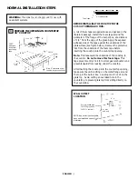
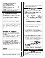
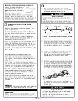
A roll of foam tape is supplied loose and packed in the
literature package. Install the foam tape around the
perimeter of the flange of the burner box, at a distance
of 1/4” from the edge of the glass. Apply the exposed
adhesive side of the tape against the underside of the
glass surface (see figure below). Remove the protective
film from the underside of the foam tape before
inserting the cooktop into the countertop opening.
Note:
This tape seals the underside of the cooktop to
the counter.
Do not remove this foam tape.
This
tape prevents entry of air for normal gas combustion and
prevents liquids from leaking under the cooktop.
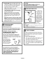
After inserting the cooktop into the countertop opening,
make sure the unit is sitting on the metal flange around
the top of the burner box. Cooktop must not sit on the
glass top. Avoid cutting an oversized hole in the
countertop to prevent glass top from sitting directly on
the countertop.
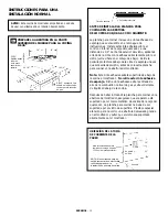
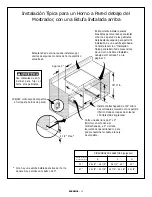
PREPARE THE OPENING IN COUNTERTOP
36” COOKTOP
3"
min.
4 1/4"
min.
34 1/4"
16 3/4"
18"
36"
3 5/32"
Measured
down from
countertop
edge.
Foam tape
Protective film
*
Allow 5” clearance under
cooktop for gas connection
*
of floor
of wall
and unit
22"
10"
8"
12"
Recommended area
for 120V grounded
outlet on rear wall.
WALL OUTLET
LOCATION
1
NOTE: If an outlet is not available,
have one installed by a qualified
electrician.

