


●
For left piping and left rear piping, align the marks on the wall
hook bracket and shape the connection pipe.
●
Bend the connection piping at a bend radius of 2 - 3/4’’(70 mm) or
more and install no more than 1- 3/8’’(35 mm) from the wall.
●
After passing the indoor piping and drain hose through the wall
hole, hang the indoor unit on the hooks at the top and bottom of
the wall hook bracket.
[Installing the indoor unit]
●
Hang the indoor unit from the hooks at the top of the wall hook
bracket.
●
Insert the spacer, etc. between the indoor unit and the wall hook
bracket and separate the bottom of the indoor unit from the wall.
Fig. 4
After hooking the indoor unit to the top hook, hook the fittings of the
indoor unit to the two bottom hooks while lowering the unit and
pushing it against the wall.
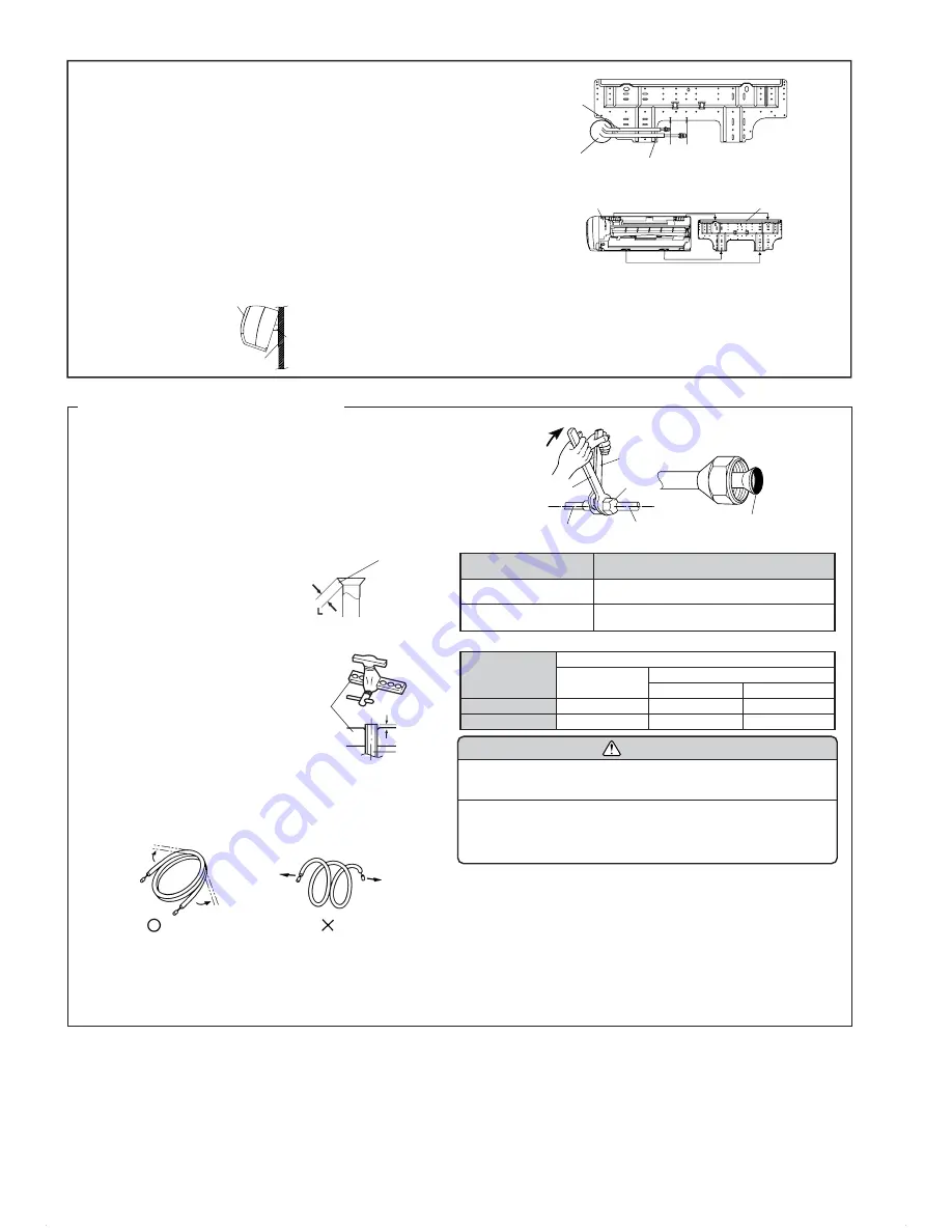
BENDING PIPES
The pipes are shaped by your hands. Be careful not to collapse them.
Do not bend the pipes in an angle more than 90°.
When pipes are repeatedly bent or stretched, the material will harden,
making it difficult to bend or stretch them any more. Do not bend or stretch
the pipes more than three times.
Top hooks
Indoor unit
Bottom hooks
Wall hook bracket
Connection pipe
(1/4” (6.35 mm)
dia.)
Connection pipe
(3/8” (9.52 mm) dia.)
Align the marks.
Bend (R70) with
a pipe bender
Indoor unit
Wall hook bracket
(Spacer)
CONNECTION
(1) Install the outdoor unit wall cap (supplied with the optional installa-
tion set or procured at the site) to the wall pipe.
(2) Connect the outdoor unit and indoor unit piping.
(3) After matching the center of the flare surface and tightening the nut
hand tight, tighten the nut to the specified tightening torque with a
torque wrench. (Table 2)
FLARING
(1) Cut the connection pipe to the nec-
essary length with a pipe cutter.
(2) Hold the pipe downward so that
cuttings will not enter the pipe and
remove the burrs.
(3) Insert the flare nut onto the pipe
and flare the pipe with a flaring
tool.
Insert the flare nut (always use the flare
nut attached to the indoor and outdoor
units respectively) onto the pipe and
perform the flare processing with a
flare tool.
Use the special R410A flare tool, or
the conventional (for R22) flare tool.
When using the conventional flare tool,
always use an allowance adjustment
gauge and secure the A dimension
shown in table 3 .
CONNECTING THE PIPING
Check if [L] is flared uniformly
and is not cracked or scratched.
Table 2
Flare nut tightening torque
Table 3
Pipe outside diameter
Flare nut
1/4” (6.35 mm) dia.
3/8” (9.52 mm) dia.
Tightening torque
11.57 to 13.20 ft
•
lbs
(160 to 180 kgf
•
cm)
21.70 to 30.38 ft
•
lbs
(300 to 420 kgf
•
cm)
A (in)
Pipe outside
diameter
1/4” (6.35 mm)
3/8” (9.52 mm)
Flare tool for
R410A, clutch type
0 to 1/32
0 to 1/32
Conventional (R22) flare tool
Clutch type
1/32 to 2/32
1/32 to 2/32
Wing nut type
2/32 to 3/32
2/32 to 3/32
CAUTION
(1) Fasten a flare nut with a torque wrench as instructed in this manual. If
fastened too tight, the flare nut may be broken after a long period of time
and cause a leakage of refrigerant.
(2) During installation, make sure that the refrigerant pipe is attached firmly
before you run the compressor. Do not operate the compressor under the
condition of refrigerant piping not attached properly with 2-way or 3-way
valve open. This may cause abnormal pressure in the refrigeration cycle
that leads to breakage and even injury.
Fig. 5
Tighten with two wrenches.
Torque
wrench
Wrench (fixed)
Flare nut
Indoor unit pipe
Connection pipe
To prevent gas leakage, coat the flare
surface with refrigerator oil.
Die
A
Pipe
OK
NO
Extend the pipe
by unwinding it.


