


VYPER
™
VARIABLE SPEED DRIVE
INSTALLATION
100-200 IOM (FEB 09)
Page 9
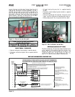
Figure 4 - Pressure Drop vs. Flow Rate
HEAT EXCHANGER PRESSURE DROP
In order to adequately size piping and booster pump require-
ments, the pressure drop of the coolant across the heat
Figure 3 - Minimum Flow Rates - GlYCOl
exchanger must be known. Figure 4 provides installation
designers with pressure drop reference for different mixtures
of propylene glycol and water.