


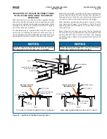


Figure 2 - AcuAir System-to-Wall Spacing Requirements
NOTES:
1.
The minimum distance from the exhaust fan housing to
any sensitive object in the discharge air stream is 2 fan
diameters. Any closer and the object may be damaged.
The minimum recommended distance from the exhaust
fan housing to an airflow obstruction (such as a wall) is
4 fan diameters for a single fan and 6 fan diameters for
two exhaust fans.
2.
The minimum distance from an access door, in the open
position, to an object is the door width, i.e. 24", plus 8".
3.
The minimum distance from any electrical enclosure to
an object is 48". The installation of the AcuAir unit must
be in accordance with the codes of the authorities having
jurisdiction.
4.
The AcuAir hygienic unit will have sections under both
positive and negative pressure with respect to ambient
during normal operation. When piping the individual
drain pan outlets to a common drain line AcuAir
recommends individual p-traps. The piping design should
take into account the pressure inside the specific section
and the elevation required to create the necessary trap.
See page 26 for help designing the drain piping.
5.
Consult the refrigeration contractor as to how much
space is required for the coil piping. A minimum walk
space of 30" should be left between the final field piping
to any object.
6.
As with any large equipment placement consideration of
maintenance, service and part/component replacement
should be allowed when designing space for the unit.
210.100-IOM (JUL 2018)
Page 7
ACUAIR
®
HYGIENIC AIR UNITS
INSTALLATION
FLOOR DRAIN
CONN. TYP.
FLAT
PREFILTERS
FINAL FILTERS
LIQUID INLET CONN. (Typ.2)
COIL OUTLET CONN. (Typ.2)
WEATHER
HOODS
SMOKE
DETECTOR
AMMONIA
DETECTOR
W
S1
S3
P-CONE
GAUGE
GAS TRAIN & CONTROLS
R1
P1
P2
R2
S2
L
S4
H
Y
FILTER PRESSURE
GAUGE (TYP. 2)
*Generic unit layout shown. Please consult the order specific unit layout drawing before beginning site engineering.
SEE NOTE 4
SEE NOTE 1
SEE NOTE 3
SEE NOTE 2
Summary of Contents for AcuAir
Page 54: ......