


MPC8572E Advanced Mezzanine Card Hardware Getting Started Guide, Rev. 1.0
Freescale Semiconductor
7
Perform Initial Board Power Up and Check LEDs
3. When powered up:
a) Blue front panel LED remains illuminated as long as power is applied to the board (via the
AdvancedMC backplane connector).
b) Ethernet port activity LEDs switch on to indicate any Ethernet link to the front or back planes.
c) The “System Status” LED, LD507, switches on, then goes off once system configuration is
complete. LED LD506 should stay on indicating the processor is “Ready.”
d) Any USB UART activity is shown on LEDs D507 and D508.
4. Pressing the power cycle button (SW2) power cycles the board and start the reset sequence.
5. Pressing the reset button (SW3) starts the reset sequence only.
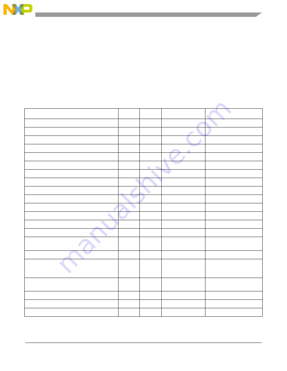
Table 5. LED Operation
Description
Ref
Color
LED On
LED Off
MMC red LED
LD1
Red
MMC control
Normal operation
MMC card power blue LED
LD500
Blue
Hot swap state
Hot swap state
Port 0 AMC SERDES Ethernet Rx activity
D500
Green
Rx Ethernet activity
No Rx Ethernet activity
Port 0 AMC SERDES Ethernet Tx activity
D501
Yellow
Tx Ethernet activity
No Tx Ethernet activity
Port 0 AMC SERDES LOS
D502
Orange
Loss of signal
No loss of signal
Port 1 AMC SERDES LOS
D504
Orange
Loss of signal
No loss of signal
Port 1 AMC SERDES Ethernet Tx activity
D505
Yellow
Tx Ethernet activity
No Tx Ethernet activity
Port 1 AMC SERDES Ethernet Rx activity
D506
Green
Rx Ethernet activity
No Rx Ethernet activity
USB/UART 1 activity
D507
Orange
UART 1 activity
No UART 1 activity
USB/UART 0 activity
D508
Orange
UART 0 activity
No UART 0 activity
Front panel dual RJ45 Ethernet Rx activity
P3:D1-2a
Green
Rx Ethernet activity
No Rx Ethernet activity
Front panel dual RJ45 Ethernet Tx activity
P3:D1-4a
Yellow
Tx Ethernet activity
No Tx Ethernet activity
Front panel dual RJ45 Ethernet Rx activity
P3:D1-2b
Green
Rx Ethernet activity
No Rx Ethernet activity
Front panel dual RJ45 Ethernet Tx activity
P3:D1-4b
Yellow
Tx Ethernet activity
No Tx Ethernet activity
Front panel 10/100 RJ45 Ethernet Rx activity
P1
Orange/
Green
Rx Ethernet activity
No Rx Ethernet activity
Front panel 10/100 RJ45 Ethernet Tx activity
P1
Yellow
Tx Ethernet activity
No Tx Ethernet activity
General debug system CPLD
LD507
Green
System CPLD
execution not
complete
System CPLD execution
complete
General debug system CPLD
LD506
Green
Ready signal
POR config cycles
unsuccessful
General debug system CPLD
LD505
Yellow
Default on
User debug #1
General debug system CPLD
LD504
Yellow
Default on
User debug #2
General debug POR CPLD
LD502
Green
User config #1
User config #1


