9
Inline 400 Installation Procedure (Plumbing)
1. Disconnect relevant electrical power at the main breaker.
2. Close all water supply valves necessary to turn off the incoming water supply. Carefully drain the existing plumbing system of all water.
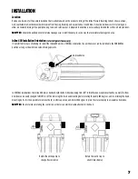
3. Mount the Inline Pressure Boosting System in the desired location using mounting screws and mounting holes. The mounting screws are
not included with the product. The Inline Pressure Boosting System may be installed in a horizontal or vertical orientation but must not be
inverted or hung from a horizontal surface.
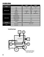
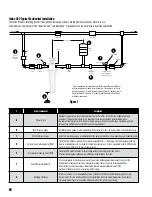
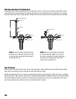
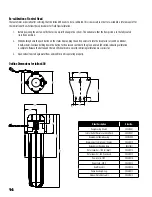
4. Install inlet and outlet plumbing and pressure tank as shown in Figure 1. The inlet and outlet of the unit is marked with “INLET” and “OUTLET”
respectively. Unions should be installed on the suction and discharge ends of the pump (use of PTFE thread sealant tape is recommended
over paste; do not overtighten). Internal check valves are provided on both the suction and the discharge ends of the pump. These valves
can help in preventing backflow. If the optional bypass loop is used, a check valve should also be installed in the bypass (see Fig. 1).
Be sure to check all local plumbing codes to ensure that all requirements pertaining to backflow prevention are met.
5. Install a pressure gauge on both the inlet and outlet pipes. These will be required in order to properly adjust the system
as well as aid in system troubleshooting.
6. Install the pressure tank downstream from the pump. The tank should be located within 5' of the discharge of the pump.
There should be no control/check valve between the pressure tank and the Inline Pressure Boosting System. The tank pre-charge pressure
shall be no greater than 2 psi below the outlet pressure switch setting & never exceed 80 psi.
7. Install a pressure relief valve downstream of the Inline 400. The discharge must be plumbed to a drain rated for
maximum pump output at relief pressure settings.
s
!
WARNING
The Inline Pressure Boosting System can develop very high pressure in some situations.
Always install a pressure relief valve able to pass full pump flow at 120 psi (6.9 bar). Install the pressure relief valve near the pressure tank.
It might be necessary to install a pressure reducing valve to limit the potential boost. Install the pressure reducing valve after the pressure tank.
Inline 400 Installation Procedure (Electrical)
1. Employ a licensed electrician to perform the wiring. All wiring must be done in accordance with applicable
national and local electrical codes.
2. Disconnect electrical power at the main breaker.
3. Verify that the dedicated branch circuit for the Inline Pressure Boosting System is equipped with a 15 amp circuit breaker.
4. Check that the power supply corresponds with the electrical rating of the Inline Pressure Boosting System being installed.
Supply voltage must be +/- 10% of the nameplate voltage.
5. Every installation must be grounded. There must be a reliable ground connection between the pump and the distribution panel.
6. The Inline Pressure Boosting System comes with all internal connections pre-wired.
7. Unit should be plugged into an outlet that matches that of the unit purchased.
Summary of Contents for Inline400
Page 1: ...INLINE PRESSURE BOOSTING SYSTEM Owner s Manual ...
Page 21: ...21 NOTES ...
Page 22: ...22 NOTES ...
Page 23: ...23 NOTES ...
Page 25: ...SISTEMA DE PRESURIZACIÓN INLINE Manual del usuario ...
Page 45: ...21 NOTAS ...
Page 46: ...22 NOTAS ...
Page 47: ...23 NOTAS ...
Page 49: ...SYSTÈME DE SURPRESSION INLINE Manual du propriétaire ...
Page 69: ...21 REMARQUES ...
Page 70: ...22 REMARQUES ...
Page 71: ...23 REMARQUES ...

