


DATA_FOCUS_ON (0x35)
Four-byte command (Sync, Lamp address, command, CRC). Sets the focus
motor running. Focus will continue to operate until a DATA_FOCUS_OFF
command is received. This command is included to allow systems which have
a low refresh rate to control the focus motor.
DATA_FOCUS_OFF (0x36)
Four-byte command (Sync, Lamp address, command, CRC). Stops the focus
motor.
Used to cancel the DATA_FOCUS_ON command. This command is included
to allow systems which have a low refresh rate to control the focus motor.
DATA_FOCUS_HEAD2_ON (0x37)
Four-byte command (Sync, Lamp address, command, CRC). Sets the head 2
focus motor running (when fitted). Focus will continue to operate until a
DATA_FOCUS_HEAD2_OFF command is received. This command is
included to allow systems which have a low refresh rate to control the focus
motor.
DATA_FOCUS_HEAD2_OFF (0x38)
Four-byte command (Sync, Lamp address, command, CRC). Stops the head2
focus motor (when fitted). Used to cancel the DATA_FOCUS_HEAD2_ON
command.
This command is included to allow systems which have a low refresh rate to
control the focus motor.
ERROR CONTROL CRC
Error control is implemented with a CRC following each data packet. The
CRC is radix to 7 bits giving a value between 0 and 127. The CRC is simply
the addition of all packets data values including the address and start byte
(0xFF). For example, a command to run lamp 0 focus motor would be 0xFF,
0x90, 0x0B. The addition of these values give 0x19A. The CRC would
therefore be this value radix to 7 bits to give a value of 0x1A. This value is
sent as the last byte of the packet.
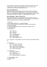
DATA TIMING
Data packets can be sent up to 10 times per second. Each packet starts with
value 0xFF. The remaining bytes should follow immediately. The whole
packet must be received within 30mS. A packet lasting longer than 30mS will
be rejected.
There is no minimum packet send rate.
When the FBUS interface receives the DATA_REQUEST_LAMP_STATUS
command there is a 2-30mS delay after which the FBUS interface switches to
transmit and outputs 13 data bytes in direct succession. After the last byte has
been sent the interface will switch back to receive.
Summary of Contents for A7290
Page 6: ......
Page 7: ......
Page 8: ...Remove front panel for AC DC wiring connections Back To Top...
Page 9: ...INPUT 4 CORE 2 5mm TE2 50mm WELDING CABLE S50 2 CORE 1 5mm D1...
Page 10: ......
Page 15: ......
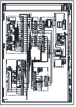
Page 22: ...FBUS Speed Control Board...
Page 50: ......
Page 51: ......
Page 52: ......
Page 53: ......
Page 54: ......
Page 55: ......
Page 56: ......
Page 57: ......


