


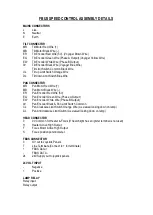


CONNECTIONS TO FBUS JOYSTICK CONTROL PANEL
FBUS CONNECTOR
0
OV Supply Input
T
Line Terminate (Connect to + for terminate)
+
FBUS + RS485 Data In/Out
-
FBUS - RS485 Data In/Out
24
+24V Supply Input
JOYSTICK CONNECTOR
BK
Joystick Black Wire
Y
Joystick Yellow Wire
BL
Joystick Blue Wire
R
Joystick Red Wire
FBUS JOYSTICK CONTROL BOARD
Summary of Contents for A7290
Page 6: ......
Page 7: ......
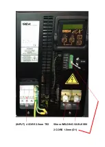
Page 8: ...Remove front panel for AC DC wiring connections Back To Top...
Page 9: ...INPUT 4 CORE 2 5mm TE2 50mm WELDING CABLE S50 2 CORE 1 5mm D1...
Page 10: ......
Page 15: ......
Page 22: ...FBUS Speed Control Board...
Page 50: ......
Page 51: ......
Page 52: ......
Page 53: ......
Page 54: ......
Page 55: ......
Page 56: ......
Page 57: ......


