Fracarro 270678 Operating Instructions Manual Download Page 48

8

DEUTSCH

Mit dieser Anleitung werden Sie von Ihrem optischen FRACAR-

RO System Höchstleistungen erzielen


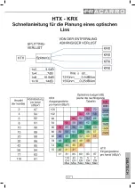
1. SCHRITT: Berechnung des optischen Budgets.

 Das erste Schema zur  Berechnung 

Ihres optischen Budgets (optischer  Verlust zwischen HTX und KRX) verwenden. Die kor-
rekte Zahl an dB hinzufügen, die der angewendeten Anzahl an Split entspricht, und für 
jeden Kilometer Faser entlang der Linie 0,4dB hinzufügen (oder 0,25dB, wenn man einen 
1550nm Sender benutzt). Wenn man zum Beispiel hat : HTX – KSP1_2 – KSP1_4 – 8km 
Faser – KRX, wird das optische Budget sein: 7 + 3.5 + 0.4 x 8 = 13.8dB (

14dB). 

Achtung: schmutzige Verbinder können das optische Budget negativ beeinflus-
sen! 

Die Verbinder sorgfältig reinigen!


2. SCHRITT: Bestimmung der optimalen Eingangs-
stärke. 


Das Schwierige ist immer die Übertragung 

analogischer Terr-Kanäle.

  Nehmen  wir  an,  dass  40 

Kanäle zu übertragen sind. Falls es die Head-end-Ap-
paratur ermöglicht, die Leistung auf den Wert in der Ta-
belle  links  einstellen  (ca.  85dBµV  unter  Bezugnahme 
auf die Reihe des Kanals 42); andernfalls sicher stellen, 
dass sie nicht überschritten wird. 

Als allgemeine Re-

gel gilt: die Leistung des Digitaltransponders muss 
um  10dB-15dB  niedriger  als  die  analogischen  Ka-
näle sein:

 wenn man zum Beispiel 30 SAT-Transponder 

hat, ist die optimale Einstellung 70-75dBµV pro Trans-
ponder. 

3.  SCHRITT:  Berechnung  von  SNR  und 
der Ausgangsstärke. 

Unter Berücksichtigung 

eines optischen Budgets von 14dB kann das 
SNR in dem Bereich zwischen der Spalte der 
Eingangsstärke und der Diagonalen des opti-
schen Budgets gelesen werden. Im vorherigen 
Beispiel ist das SNR für analogische Kanäle  
51dB. Die  Ausgangsstärke kann gelesen wer-
den,  indem  man  sich  nach  links  bewegt,  bis 
man auf die letzte Spalte trifft: im Beispiel ist 
sie 82dBµV für jeden analogischen Kanal. 
Für digitale Transponder wendet man ähnliche 
Erwägungen  an. Wenn  man  sowohl  DTT  als 
auch die Leistung des SAT-Transponders auf 
10dB weniger als an den analogischen Terr-
Transpondern  einstellt,  wird  auch  die    Aus-
gangsstärke unter 10dB sein, und SNR wird unter 10dB sein, was aber für die digitalen 25dB 
Signale von SNR immer noch ein guter Wert ist! 

Weitere Beispiele befinden sich in der  Bedienungsanleitung – bitte genau lesen! 

Summary of Contents for 270678

Page 1: ...USO OPERATING INSTRUCTIONS INSTRUCTIONS D EMPLOI INSTRUCCIONES DE USO INSTRU ES DE FUNCIONAMENTO BETRIEBSANLEITUNG SIG7600 HTX TRASMETTITORE OTTICO OPTICAL TRANSMITTER METTEUR OPTIQUE TRANSMISOR PTICO...

Page 2: ...rica Il collegamento alla corrente elettrica deve essere eseguito da personale idoneo e competente in conformit alle locali normative di sicurezza Sicurezza e precauzioni Il prodotto dichiarato di Cla...

Page 3: ...ttamente alimentato e atten dere alcuni secondi utilizzando il modulo TPE entrare nel men SETUP CENTRALE SCAN CEN TRALE avvenuta l acquisizione dei moduli entrare in SETUP CENTRALE NAVIGA ZIONE XX SIG...

Page 4: ...radiazione luminosa coerente Spento il laser non attivato nessuna radiazione emessa dal modulo Over current Rosso Acceso la corrente che alimenta il diodo laser sta eccedendo i limiti di corretto funz...

Page 5: ...memorizzare i dati impostati premere il tasto S del TPE Se non si preme il tasto S entro i 5 minuti dell ultima modifica i dati impostati verranno persi Per maggiori dettagli vedere le istruzioni del...

Page 6: ...2 portanti CSO CTB 60dBc Max livello SAT 92dB V 2 toni IM3 35dBc Return Loss 10dB Lunghezza d onda 1310 10nm Potenza ottica 13mW 11 dBm Piattezza in banda 47 862MHz 1 dB Piattezza in banda 950 2150MHz...

Page 7: ...ITALIANO...

Page 8: ...circa 85dB V riferendosi alla fila del canale 42 altrimenti assicurasi di non superarla Come regola generale la potenza del transponder digitale deve essere pi bassa di 10dB 15dB dei canali analogici...

Page 9: ...nte alcool puro sul bordo della ferula poi togliere lo sporco con uno spruzzo Prima di inserire nuovamente tutti i connettori pulire l adattatore applicando una goccia di liquido pulente nel foro cent...

Page 10: ...ection to the power must be performed by trained and skilful personnel according to local safety norms Safety and precautions the product of Class II in conformity with the EN 60065 regulation must be...

Page 11: ...he HEAD LINE basket and power supply it properly wait for few seconds use the TPE module to enter the EXCHANGE SETUP menu SCAN EX CHANGE after the acquisition of the modules enter EXCHANGE SETUP NAVIG...

Page 12: ...r is activated and is emitting a luminous radiation Off the laser is not activated no radiation emits from the module Over current Red On the power that supplies the laser diode is exceeding the limit...

Page 13: ...n within 5 minutes of the last change the data set will be lost For more details see rack mounting operating instructions The modulators programming menu is shown below To remove the module use the ha...

Page 14: ...42 carriers CSO CTB 60dBc Max livello SAT 92dB V 2 tones IM3 35dBc Return Loss 10dB Wavelength 1310 10nm Optical power 13mW 11 dBm Flatness in 47 862MHz band 1 dB Flatness in 950 2150MHz band 2 dB Pow...

Page 15: ...15 ENGLISH...

Page 16: ...r power to the value suggested by the table on the left about 85dB V referring to the 42ch row otherwise make sure you aren t exceeding it As a general rule digital transponders power must be 10dB 15d...

Page 17: ...nt pure alcohol on the ferule edge and then remove dust with a spray Before inserting all of the connectors clean the adapter by applying a drop of a cleansing agent in the central hole and then remov...

Page 18: ...onnexions au courant lectrique la connexion au courant lectrique doit tre effectu e par le personnel sp cialis et comp tent conform ment aux normes de s curit en vigueur S curit s et pr cautions le pr...

Page 19: ...la s rie HEADLINE correctement aliment et attendre quelques secondes en utilisant le module TPE entrer dans le menu REGLAGE CENTRALE SCAN CENTRALE lorsque l acquisition des modules a t r alis e entrer...

Page 20: ...et met une radiation lumineuse coh rente Eteinte le laser n est pas activ aucune radiation n est mise par le module Over current Rouge Allum e le courant qui aliment la diode laser d passe les limite...

Page 21: ...odification toutes les donn es rentr es seront perdues Pour plus de d tails voir le mode d emploi du support rack Le menu concernant la programmation des modulateurs se trouve ci dessous Pour enlever...

Page 22: ...CTB 60dBc Niveau max SAT 92dB V 2 tonalit s IM3 35dBc Return Loss Perte de retour 10dB Longueur d onde 1310 10nm Puissance optique 13mW 11 dBm Platitude en bande 47 862MHz 1 dB Platitude en bande 950...

Page 23: ...23 FRAN AIS...

Page 24: ...se r f rant la ligne du canal 42 dans le cas contraire faire atten tion ne pas la d passer En g n ral la puissance du transpondeur num rique doit tre inf rieure de 10dB 15dB par rapport aux canaux an...

Page 25: ...l pur sur le bord de la f rule et retirer la salet l aide du vaporisateur Avant d ins rer les connecteurs nettoyer l adaptateur en appliquant une goutte de liquide nettoyant dans le trou central et l...

Page 26: ...la corriente el ctrica La conexi n a la corriente el ctrica tiene que llevarla a cabo personal id neo y competente con arreglo a las normativas de seguridad locales Seguridad y precauciones El product...

Page 27: ...rrecta y espere unos segundos Utilizando el m dulo TPE entre en el men SETUP CENTRAL SCAN CEN TRAL Una vez adquiridos los m dulos entre en SETUP CENTRAL NAVEGACI N XX SIG7600 HTX donde XX indica la po...

Page 28: ...herente Apagado el l ser no est activado y el m dulo no emite ninguna radiaci n Over current Rojo Encendido la corriente que alimenta el diodo l ser est superando los l mites de funcionamiento correct...

Page 29: ...s ajustados pulse la tecla S del TPE Si en un plazo de tiempo de 5 minutos desde la ltima modificaci n no se pulsa la tecla S se pierden los datos ajustados Para m s informaci n v anse las instruccion...

Page 30: ...s CSO CTB 60dBc M x nivel SAT 92dB V 2 tonos IM3 35dBc Return Loss P rdida de retorno 10dB Longitud de onda 1310 10nm Potencia ptica 13mW 11 dBm Desenfoque en banda 47 862MHz 1 dB Desenfoque en banda...

Page 31: ...31 ESPA OL...

Page 32: ...a la fila del canal 42 si no aseg rese de no superarla Como regla general la potencia del transponde dor digital tiene que ser inferior a 10 dB 15 dB respecto a los canales anal gicos por ejemplo si...

Page 33: ...en el borde de la f rula y luego elimine la suciedad con un chorro Antes de conectar de nuevo todos los conectores limpie el adaptador aplicando una gota de l quido limpiador en el orificio central y...

Page 34: ...es corrente el ctrica A liga o corrente el ctrica deve ser executada por pessoal adequado e competente em conformidade com as normas de seguran a locais Seguran a e precau es O produto foi declarado d...

Page 35: ...LINE correctamente alimentado e aguarde alguns segundos utilizando o m dulo TPE entre no menu SETUP CENTRAL SCAN CENTRAL efectuada a aquisi o dos m dulos entre em SETUP CENTRAL NAVEGA O XX SIG7600 HTX...

Page 36: ...itir radia o luminosa coerente Apagado o laser n o est activado nenhuma radia o emitida do m dulo Over current Vermelho Aceso a corrente que alimenta o d odo laser est a exceder os limites de funciona...

Page 37: ...ara memorizar os dados programados carregar na tecla S do TPE Se a tecla S n o for pressionada dentro de 5 minutos ap s a ltima modifica o os dados programados perder se o Para maiores detalhes veja a...

Page 38: ...anti CSO CTB 60dBc N vel m x SAT 92dB V 2 toni IM3 35dBc Return Loss Perda de retorno 10dB Comprimento de onda 1310 10nm Pot ncia ptica 13mW 11 dBm Planeza na banda 47 862MHz 1 dB Planeza na banda 950...

Page 39: ...39 PORTUGU S...

Page 40: ...erca de 85dB V referindo se fila do canal 42 caso contr rio tenha a certe za de que n o a supera Via de regra a pot ncia do transponder digital deve ser mais baixa de 10dB 15dB em rela o aos canais an...

Page 41: ...quido de limpeza lcool puro na borda da f rula depois retire a sujidade com um borrifo Antes de inserir novamente todos os conectores limpe o adaptador aplicando uma gota de l quido de limpeza no fur...

Page 42: ...omnetz muss von sachkundigem und geeignetem Personal in bereinstimmung mit den rtlichen Sicherheitsvorschriften ausgef hrt sein Sicherheit und Vorsichtsma nahmen Das Produkt geh rt in Konformit t mit...

Page 43: ...orrekt gespeisten HEAD LINE Korb stecken und ein paar Se kunden warten das TPE Modul verwenden und in das Men SETUP ZENTRALE SCAN ZEN TRALE gehen nach der erfolgten Erfassung der Module in SETUP ZENTR...

Page 44: ...ON Gr n Ein Laser aktiviert und gibt entsprechende Leuchtstrahlung ab Aus Laser nicht aktiviert keine Strahlungsabgabe durch das Modul Over current Rot Ein der Strom der die Laserdiode speist berschr...

Page 45: ...die eingestellten Daten zu speichern auf Taste S am TPE dr cken Die eingestellten Daten gehen verloren wenn man nicht innerhalb von 5 Minuten ab der letzten nderung auf Taste S dr ckt F r weitere Einz...

Page 46: ...V 42 tragend CSO CTB 60dBc Max SAT St rke 92dB V 2 T ne IM3 35dBc Return Loss 10dB Wellenl nge 1310 10nm Optische Leistung 13mW 11 dBm Bandflachheit 47 862MHz 1 dB Bandflachheit 950 2150MHz 2 dB Vers...

Page 47: ...47 DEUTSCH...

Page 48: ...e des Kanals 42 andernfalls sicher stellen dass sie nicht berschritten wird Als allgemeine Re gel gilt die Leistung des Digitaltransponders muss um 10dB 15dB niedriger als die analogischen Ka n le sei...

Page 49: ...anbringen dann den Schmutz mit einem Spritzger t entfernen Bevor alle Verbinder erneut eingef gt werden den Adapter mit einem Tropfen Fl ssigreiniger in das Loch in der Mitte reinigen und sofort mit e...

Page 50: ...50...

Page 51: ...51...

Page 52: ...negocios c 2A n 4 46980 Paterna Valencia ESPA A Tel 34 961340104 Fax 34 961340691 Fracarro UK Ltd Unit A Ibex House Keller Close Kiln Farm Milton Keynes MK11 3LL UK Tel 44 0 1908 571571 Fax 44 0 1908...

Reviews: