background image

4

ET2707


OBDII/EOBD


Code


Reader


User’s


Guide_English


Version_V1.00

Safety Information

For your own safety and the safety of others, and to prevent damage to the equipment and

vehicles, read this manual thoroughly before operating your code reader. The safety messages

presented below and throughout this user’s manual are reminders to the operator to exercise

extreme care when using this device. Always refer to and follow safety messages and test

procedures provided by vehicle manufacturer. Read, understand and follow all safety messages

and instructions in this manual.

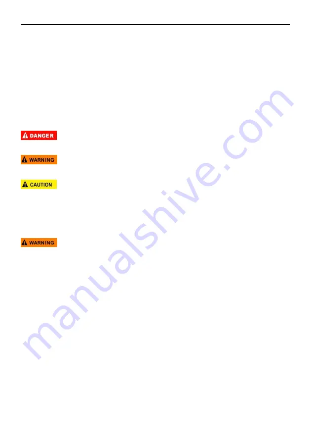
Safety Message Conventions Used

We provide safety messages to help prevent personal injury and equipment damage. Below are

signal words we used to indicate the hazard level in a condition.

Indicates an imminently hazardous situation which, if not avoided, will result in death or serious

injury to the operator or to bystanders.

Indicates a potentially hazardous situation which, if not avoided, could result in death or serious

injury to the operator or to bystanders.

Indicates a potentially hazardous situation which, if not avoided, may result in moderate or minor

injury to the operator or to bystanders.

Important Safety Instructions

And always use your code reader as described in the user’s manual, and follow all safety

messages.

Do not route the test cable in a manner that would interfere with driving controls.

Do not exceed voltage limits between inputs specified in this user’s manual.

Always wear ANSI approved goggles to protect your eyes from propelled objects as well as hot

or caustic liquids.

Fuel, oil vapors, hot steam, hot toxic exhaust gases, acid, refrigerant and other debris produced

by a malfunction engine can cause serious injury or death. Do not use the code reader in areas

where explosive vapor may collect, such as in below-ground pits, confined areas, or areas that

are less than 18 inches (45 cm) above the floor.

Do not smoke, strike a match, or cause a spark near the vehicle while testing and keep all

sparks, heated items and open flames away from the battery and fuel / fuel vapors as they are

highly flammable.

Keep a dry chemical fire extinguisher suitable for gasoline, chemical and electrical fires in work

area.

Always be aware of rotating parts that move at high speed when an engine is running and keep

a safe distance from these parts as well as other potentially moving objects to avoid serious

injury.

Do not touch engine components that get very hot when an engine is running to avoid severe

burns.

Block drive wheels before testing with engine running. Put the transmission in park (for

automatic transmission) or neutral (for manual transmission). And never leave a running engine

unattended.

Do not wear jewelry or loose fitting clothing when working on engine.

Summary of Contents for ET2707

Page 1: ...Test On board Monitor Test Component Test Vehicle Information Modules Present Unit of measure DTC GUIDE Pictures illustrated here are for reference only and this Quick Start Guide is subject to change...

Page 2: ...itch is turned to the ON position 2 That the vehicle s engine is off 3 The vehicle battery voltage is between 12 14 volts Don t connect or disconnect the code reader while the ignition is on or the en...

Page 3: ...holders Copyright Information 2014 Shenzhen Foxwell Technology Co Ltd All rights reserved Disclaimer The information specifications and illustrations in this manual are based on the latest informatio...

Page 4: ...g the product back to the customer after the completion of service under this limited warranty 4 FOXWELL does not warrant uninterrupted or error free operation of the product If a problem develops dur...

Page 5: ...CONTRACT NEGLIGENCE STRICT TORT OR ANY OTHER LEGAL OR EQUITABLE THEORY EVEN IF FOXWELL KNEW OF THE LIKELIHOOD OF SUCH DAMAGES FOXWELL SHALL NOT BE LIABLE FOR DELAY IN RENDERING SERVICE UNDER THE LIMIT...

Page 6: ...llow all safety messages Do not route the test cable in a manner that would interfere with driving controls Do not exceed voltage limits between inputs specified in this user s manual Always wear ANSI...

Page 7: ...2 1 CODE READER DESCRIPTIONS 8 2 2 ACCESSORY DESCRIPTIONS 8 2 3 TECHNICAL SPECIFICATIONS 9 3 GETTING STARTED 9 3 1 PROVIDING POWER TO CODE READER 9 3 1 1 CONNECTING TO VEHICLE POWER 9 3 1 2 CONNECTIN...

Page 8: ...ORS 24 5 2 4 RESET FACTORY DEFAULT 25 5 3 UNIT OF MEASURE 25 5 4 KEY BEEP SET 26 5 5 DIAG BEEP SET 27 5 6 TOOL SELF TEST 28 5 6 1 DISPLAY TEST 28 5 6 2 KEYPAD TEST 28 5 6 3 LED TEST 29 6 TOOL INFORMAT...

Page 9: ...options displays Menu options include Languages Configure monitors Unit of measure Key Beep Set Diag Beep Set Tool self test 1 2 2 Arrow Icon An arrow icon indicates a procedure Example To change men...

Page 10: ...the tool finds a possible problem Pending DTCs exist or and some of the vehicle s emission monitors have not run their diagnostic testing E Red LED Display indicates there are some problems in one or...

Page 11: ...with the code reader 3 1 Providing Power to Code reader Before using the code reader make sure to provide power to the code reader The unit operates on any of the following sources 12 volt vehicle po...

Page 12: ...rame data Service 03 request emission related diagnostic trouble codes Service 04 clear reset emission related diagnostic information Service 05 request emission related diagnostic trouble codes detec...

Page 13: ...ets you read stored codes and pending codes found in the control unit Typical menu options include Stored Codes Pending Codes Diagnostic trouble codes stored in a control module are used to help ident...

Page 14: ...ption displays Figure 4 5 Sample DTC Description Screen NOTE If no DTCs are present the message No Pending Codes Found is displayed If any manufacturer specific or enhanced codes detected ET2707 reads...

Page 15: ...ear codes 1 Use the UP DOWN key to highlight Erase Codes from Diagnostic Menu and press the ENTER key Figure 4 6 Sample Diagnostic Menu Screen 2 Follow the on screen instructions and answer questions...

Page 16: ...ive PID data 1 Use the UP DOWN key to highlight Live Data from Diagnostic Menu and press the ENTER key Figure 4 8 Sample Diagnostic Menu Screen 2 Select Complete Data Set from the menu and press the E...

Page 17: ...vehicle operating conditions automatically recorded by the on board computer at the time of the DTC set It is a good function to help determine what caused the fault To view freeze frame data 1 Selec...

Page 18: ...pport that monitor There are two ways to retrieve I M Readiness Status data One click I M readiness key Typical way select I M Readiness from Diagnostic Menu NOTE To review I M Readiness status make s...

Page 19: ...eeper works with the colored LED simultaneous as an assistance to reflect the I M Readiness test results Green two long beeps Yellow short long short beeps Red four short beeps NOTE The built in beepe...

Page 20: ...icle control module s calibration verification numbers CVN s and in use performance tracking on model year 2000 and newer OBD II compliant vehicles CVNs are calculated values required by OBD II regula...

Page 21: ...end the command to read vehicle information A screen with a list of available options displays Figure 4 20 Sample Vehicle Info Screen 3 Use the UP DOWN key to highlight an available option and press t...

Page 22: ...monitors Unit of measure Key Beep Set Diag Beep Set Tool self test 5 1 Select Language Selecting Language opens a screen that allows you to choose system language To configure system language 1 Use th...

Page 23: ...us monitors Continuous monitors are being constantly tested and evaluated by the car s computer while the car is running Conversely the non continuous monitors require certain conditions to be met bef...

Page 24: ...monitors to be configured displays Figure 5 5 Sample Configure Monitors Display 5 2 1 Spark IGN Required Monitors In this menu the operators can configure monitors for spark ignition cars gasoline en...

Page 25: ...sequence of currently selected monitor 5 2 2 Compression IGN Required Monitors In this menu the operators can configure monitors for compression ignition cars diesel engines To configure spark compres...

Page 26: ...meet different standards which allows the user to select 0 1 2 3 INC monitors in test To configure allowed INC monitors 1 Use the UP DOWN key to highlight Allowed INC Monitors from the menu and press...

Page 27: ...t to 1 To reset factory default 1 Use the UP DOWN key to highlight Reset Factory Default from the menu and press the ENTER key to confirm Figure5 12 Sample Configure Monitors Selection Screen 2 A mess...

Page 28: ...Figure 5 15 Sample Unit Selection Screen 5 4 Key Beep Set Key beep set opens a dialog box that allows you to turn on off the built in speaker for key pressing To set the key beep 1 Use the UP DOWN ke...

Page 29: ...box that allows you to turn on off the built in speaker when performing diagnostics To set the diag beep 1 Use the UP DOWN key to highlight Diag Beep Set from Setup menu and press the ENTER key Figur...

Page 30: ...o check the functionality of the display To test the display 1 Use the UP DOWN key to highlight Display Test from Setup menu and press the ENTER key to start test Figure 5 20 Sample Tool Self test Scr...

Page 31: ...gure 5 23 Sample Key Test Screen 5 6 3 LED Test Selecting LED Test option opens a screen that allows you to check the functionality of the LED To test the LED 1 Use the UP DOWN key to highlight LCD Te...

Page 32: ...show information about your code reader such as serial number and software version To view information of your code reader 1 Use the LEFT RIGHT key to highlight About from home menu and press the ENT...

Page 33: ...ble to use update tool PC or laptop must meet the following minimum requirements Operation System Win98 NT Win ME Win2000 Win XP VISTA and Windows 7 CPU Intel P or better RAM 64MB or better Hard Disk...

Page 34: ...offline the update tool NT Wonder will detect these local files automatically and display them in a list Ticking one of them will lead to an update process which eliminates the need to download any f...

Page 35: ...Figure 7 5 Sample User Manual Screen 7 4 Update Tool Settings Settings option opens a screen that allows you to set the language and style of the tool Still it offers the option for you to automatica...

Reviews: