Chapter 2 Installation Instructions
16
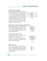
Audio Connector: F_AUDIO
The audio interface provides two kinds of au-
dio output choices: the Front Audio, the Rear
Audio. Their priority is sequenced from high to
low (Front Audio to Rear Audio). If headphones
are plugged into the front panel of the chassis
(using the Front Audio), then the Line-out (Rear
Audio) on the rear panel will not work. If you do
not want to use the Front Audio, pin 5 and 6,
pin9 and 10 must be short, and then the signal
will be sent to the rear audio port.
Besides four USB ports on the rear panel, the
series of motherboards also have two or three
10-pin connectors on board which may connect
to front panel USB cable(optional) to provide
additional four USB ports.
F_AUDIO
AUD_OUT-L
NA
MIC_IN
MIC_PWR
AUD_OUT-R
MIC_GND
+5VA
AUD_RET-R
AUD_RET-L
Empty
1
USB Connectors: F_USB1, F_USB2, F_USB3 (optional)
1
5V_DUAL
F_USB1/2/3
D-
D+
D-
GND
GND
D+
NC
Empty
5V_DUAL
Addtional COM Connector: COM2
This motherboard provides an additional serial
COM connector for your machine.
Connect one side of a switching cable to the
connector, then attach the serial COM device
to the other side of the cable.
SOUT
GND
RLSD
RI#
DTR#
DSR#
SIN
9
10
1
2
CTS#
RTS#
COM2
Empty
IrDA Connector: IR
This connector supports wireless transmit-
ting and receiving device. Before using this
function, configure the settings of IR Mode
from the
“
Integrated Peripherals
”
section of
the CMOS Setup.
IR
1
+5V
GND
IRRX
IR T X
Emp ty

