


45
WARNING
: Before switching on the machine be sure that there is not any object on the
workbench, that the riving knife is correctly placed and that the protective cap and that the blade
is assembled, is not damaged and that it works perfectly.
To start the saw, press the « I » green button (
Fig. 31
).
To stop the saw, push the « O » red button (
Fig. 32
).
The switch of this machine is a “minimum voltage“ switch and prevents the start of the machine
in case of recovery of the electrical energy after an interruption. So, you must press the green
button to re-start the saw that has stopped.
CAUTION
: Before adjusting blade’s height, loosen the locking lever of the blade (20) and tighten
it when you reach the desired position (
Fig. 33
).
1.
Place the saw blade in the desired cutting height by rotating the handle for the adjustment
of cutting height (19) (
Fig. 34
) .
2.
To increase cutting depth, rotate the handle anti-clockwise.
3.
To decrease cutting depth, rotate the handle clockwise.
The rip fence must be perfectly parallel to the saw blade.
1.
Use the rip fence if you want to cut longitudinally.
2.
The rip fence (13) can be assembled on both sides of the workbench (1). To lock it, tighten
the two wing screws (
Fig. 35
).
3.
To use the graduated scale (15) of the rip fence, move the rip fence until it reaches the
blade and measure the desired cutting on the scale (
Fig. 36
). Then move the guide away
from the saw blade. The distance between the rip fence and the saw blade corresponds to
cutting width. It is necessary to do a shear test, measure the workpiece and adjust the rip
fence in order to cut more precisely.
4.
Remove the locking lever of the saw blade (14) then position the rip fence in the desired
position (
Fig. 37
).
5.
Lastly, lower the locking lever of the rip fence (14).
1.
Place the mitre gauge (16) in the workbench’s groove (1).
2.
Loosen the mitre gauge’s handle (
Fig. 38
).
3.
Rotate the mitre gauge and select the desired angle (
Fig. 39
).
4.
Tighten mitre gauge’s handle.
START OF THE TABLE SAW
ADJUSTMENT OF CUTTING DEPTH
USE OF THE RIP FENCE
USE OF THE MITRE GAUGE
Summary of Contents for F36-521
Page 3: ...3 FIGURE ILLUSTRATIVE ...
Page 4: ...4 ...
Page 5: ...5 ...
Page 17: ...17 La macchina è composta da DESCRIZIONE DEL BANCO SEGA ...
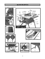
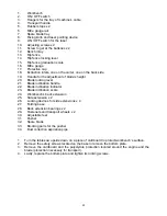
Page 40: ...40 The machine is composed by MACHINE DESCRIPTION ...
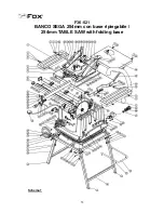
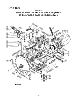
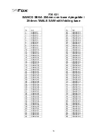
Page 53: ...53 F36 521 BANCO SEGA 254mm con base ripiegabile 254mm TABLE SAW with folding base Schema 1 ...
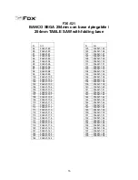
Page 54: ...54 F36 521 BANCO SEGA 254mm con base ripiegabile 254mm TABLE SAW with folding base Schema 2 ...


