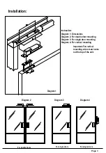
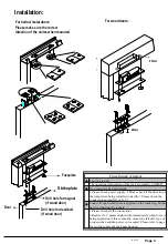
background image

Installation: 

For double doors 

For single doors 

For single doors 

Important-For vertical 
mounting, wires must come 
out the top of the unit. 

Instruction: 
Diagram 1: Dimensions 
Diagram 2: For double door mounting 
Diagram 3: For single door mounting 
Diagram 4: For vertical mounting 

Diagram 1 

Diagram 2 

Diagram 3 

Diagram 4 

Page  3 

Summary of Contents for F-S2000

Page 1: ...POINT FACE PLATE 200mm L x32mm W x40mm D STRIKE PLATE 90mm L x26mm W x2mm D PUSH BUTTON AP 10 DC 12V 1A DC12V RED N O F S2000 N C COM READER ORANGE Please switch on the appliance again to validate any adjustment of DIP switch value 0 SEC 2 5 SEC 5 SEC 9 SEC Setting door lock delay timer BROWN F S2000 6 PIN RED DC12V BROWN GND YELLOW DOOR POSITION SENSOR N C GREEN DOOR POSITION SENSOR COM ORANGE PU...

Page 2: ...ims 5 x 8 mm Strike plate template Time sec X4 Small metal screws for strike plate and shims 4 x 26 mm X 2 Large wood screws for lock body 5 x 15 mm 0 1 2 3 4 5 6 7 8 9 10 11 12 13 14 15 900 800 700 400 600 500 300 200 100 Delay Time Setting Start Stand by Door Close 0 10 20 30 40 50 60 70 80 90 100 110 120 130 140 150 65 60 55 40 50 45 35 30 25 70 Current mA Time sec Time min Temperature Supply p...

Page 3: ...doors Important For vertical mounting wires must come out the top of the unit Instruction Diagram 1 Dimensions Diagram 2 For double door mounting Diagram 3 For single door mounting Diagram 4 For vertical mounting Diagram 1 Diagram 2 Diagram 3 Diagram 4 Page 3 ...

Page 4: ...lease check power supply 2 Please check if the direction of the template is being installed correctlly 3 Please check the connection points N O or N C Lock will open when force is applied on the reader eg Hitting hard or vibrating the reader 1 Please check all the connections 2 Reader s N C points might strike immediately when force is being applied on it this eventually causes the fail safe type ...

Reviews: