


VEHICLE SAFETY CONTROLLER
© 2021, FORT Robotics. Company Confidential. Do not distribute.
935-0003 Rev C
11 of 33
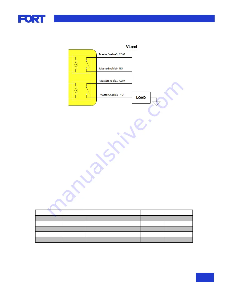
Figure 8
–
Master Enable Connection to External Load
6.
Operation
All command and control communication to the VSC is over the USB, RS232, or CAN-based interfaces. The
specific protocols for each are defined in detail below. The VSC also provides an Emergency Stop interface for
hardware based emergency control. Two Master Enable (normally high, low asserted) outputs are provided.
Two normally-closed Emergency Stop inputs are also provided, so the VSC can be connected to an existing
Emergency Stop interface. If the Emergency Stop input is activated, the Master Enable signals are asserted
immediately by VSC hardware.
The Safe Remote Control System has five modes while operating: Local, Remote, Operational, Menu, and
Pause. The basic features of these modes are summarized in Table 12. The SRC features 6-axis control, 8
buttons, and an emergency stop but the joystick and button data are only available when the system is in
operational mode as described below.
If a Wireless Emergency Stop or another Vehicle Safety Controller is paired to the primary VSC, then there will
only be two possible modes while operating: Local and Operational. In this instance, joystick information will
always be zeroed.
Mode
Value (Hex)
Heartbeat
Joysticks
Buttons
Local
0x04
Nominal / E-Stop Indicated
Zeroed
Zeroed
Remote
0x06
Nominal
Zeroed
Zeroed
Operational
0x09
Nominal
Active
Active
Menu
0x0A
Nominal
Zeroed
Zeroed
Pause
0x0B
Nominal
Zeroed
Zeroed
Table 12: VSC Modes of Operation