P a g e
|
34
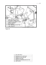
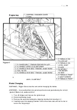
All drive belts are located under the engine cover as shown in Figure 16 and Figure
17 and tension checked at arrows shown in Figure 21. Check and set tension as
follows:
1. Slacken clamp screw(s) or nut (6).
2. Hydraulic pump adjuster screw requires its lock nut to be slackened (5).
3. Turn adjuster nut or screw (4) to tension belt until 4.5Kg force at the belt
longest centre span deflects by 6mm (see Figure 21). Can be approximated
by firmly gripping belt between finger and thumb and twisting. The belt should
not be able to be rotated more than 90°.
4. Tighten all lock nuts, nuts and clamp screws (5 & 6).
5. Run machine and test.
6. Check belt tension.
Figure 21
1 FLYWHEEL DRIVE BELTS.
CHECK TENSION HERE
2 HYDRAULIC PUMP DRIVE BELT. CHECK TENSION
HERE
3 HYDRAULIC OIL LEVEL IN SIGHT GLASS
Summary of Contents for TR6
Page 5: ...P a g e 4 ...


