background image


- 5 - 

3.


INSTALLATION LOCATION 

3.1.


Installation location 

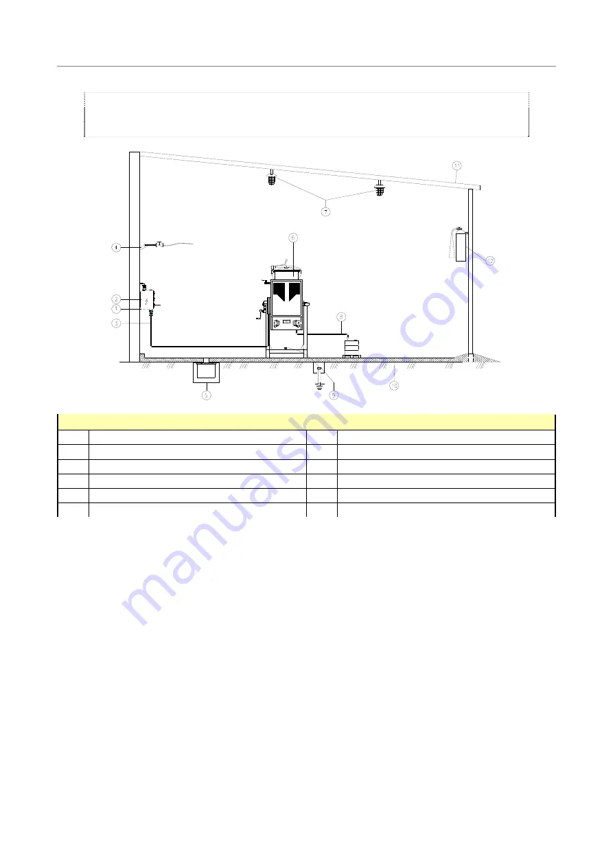
For the correct installation of the distillation unit it is necessary to classify the risk area, and as-
sure a proper ventilation and the use of certified electrical and non-electrical equipment  ac-
cording to ATEX 95 (directive 94/9/EC)     


LEGEND 

Feed box 

Lighting 

Fuses or magnet switch 

Distillate outlet 

Feeding cable 

Earth connection 

Compressed air connection (for optionals) 

10 

Containment basement 

Collection reservoir 

11 

Roof 

Distillation unit 

12 

Fire extinguisher 

 
It is necessary to install fire extinguishers (12), in correct places and in adequate number. The extinguishers must be for 
fires of class B (fires of inflammable liquids) and class C (inflammable gas fires). Warning signs have to be installed 
bringing attention to the possible dangers. 
If the machine is installed outside, it has to be protected by a roof (13). 
When treating flammable solvents, all electrical equipment present (lighting, sockets, etc.) have to be installed according 
to the existing norms regarding the areas of explosion risk. 

a.


Containment bund 

The containment bund (10) for machines up to 120 litres can be formed by a metallic bund. For bigger ma-
chines the floor can be in cement with a small wall, to contain accidental spillage. The volume of the bund 
should be at least 1.5 times the amount of solvent in the machine. 
The basement should have a slight slope (1%) towards the collection reservoir (5).


b.


Collection reservoir 

To collect accidental spills. 
The collection reservoir should have a size to be able to install a pump to remove the accidentally spilled sol-
vent (e.g..: 500 x 500 x depth 600 mm). 

Summary of Contents for Drester 120

Page 1: ...INSTR 11213 1 REV 14 04 08 Bom GODK DRESTER 120 USE and MAINTENANCE ENGLISH...

Page 2: ...uctions Rev 3 00 All rights reserved Nothing from this publication is allowed to be copied in any way whether electronically mechanically or by photo copy or in any other way without prior permission...

Page 3: ...5 2 Solvent loading 9 5 3 Cover closing 10 5 4 Programming of the working cycle 10 5 5 Stop of the unit 12 5 6 Residue unloading 12 5 7 Important advices 13 6 SAFETY SYSTEMS AND ALARMS 14 6 1 Temperat...

Page 4: ...ottom of the boiler and can easily be unloaded at the end of the cycle The boiling of the polluted solvent takes place in a boiler surrounded by a cavity space containing diathermic oil heated by an e...

Page 5: ...erature C 195 for T3 machines or 225 for T2 machines Sound level dB A 64 Geometric boiler volume litres 19 Loading volume liters 12 15 Compressed air connection for vacuum BSP1 3 8 F Pressure min max...

Page 6: ...flammable gas fires Warning signs have to be installed bringing attention to the possible dangers If the machine is installed outside it has to be protected by a roof 13 When treating flammable solven...

Page 7: ...he power supply coincide with the data on the identification tag of the machine Install a power supply 2 together with main switch for the machine n 3 fuses or magnet switches set at 50 over the absor...

Page 8: ...area should remain free to be able to access all parts of machine if necessary a Packing Remove the machine from the transport hole A and slide it into hole B install the washer provided Lock the rot...

Page 9: ...for all solvents 4 2 Connecting the distillate tank Put a container of proper size in line with the distillate discharge nozzle To connect the nozzle with the con tainer it is advisable to use a solve...

Page 10: ...ot be used for group IIB and IIC The use of non original bags can provoke fire or explosion risks due to the accumulation of electrostat ic charge on the bags during distillation It is therefore prohi...

Page 11: ...equipped with a lateral loading pipe for easy connection to the washing booth 5 5 Cover closing 1 Hook the cover closing handle over the cover bar When closing the cover pay attention not to damage t...

Page 12: ...or setting a new process time place the knob in the position OFF and repeat the setting operation above 0 2 1 5 Machine working In the display is indicated the active heating by the symbol and the cou...

Page 13: ...cle lasts for 3 4 hours For drying the residue this time can be prolonged with 15 30 minutes Distillation time depends on the type of solvent distilled as well as the degree of contamination The indic...

Page 14: ...have formed on the bottom of the boiler can be removed like described above 5 9 Important advice Do not rotate or shake the unit once loaded or when operating Clean the oil expansion vessel only with...

Page 15: ...ify the reason for the thermostat intervention if necessary replace the defective thermostat 4 push the reset button on the thermostat to reset it c Distillate temperature ST3 Maximum thermostat on co...

Page 16: ...igher than dis tiller maximum working temperature Change the solvent with one that has a lower boiling point or distil under vacuum with suitable kit optional The working thermostat is defect Change t...

Page 17: ...the suitable gasket Smoke comes out from under the cover Overheating of the polluting products or presence of nitrocellulose Reduce the working time and or temper ature Possibly distil under vacuum w...

Page 18: ...at its optimum b Check diathermic oil Check the diathermic oil level in the oil expansion vessel when the unit is cold If necessary top up the level 8 3 Weekly maintenance a Cleaning of the condensat...

Page 19: ...hout loading the machine turn the unit on at maximum temperature Having reached the maximum temperature add slowly in two or three times the remain ing oil in the expansion vessel until the expansion...

Page 20: ...element it is convenient to also change the diathermic oil and in this case it can be poured directly into the hole of the element d Reset the hour counter 1 Open the control box 2 Push the button A...

Page 21: ...to be discharged manually Automatic vacuum at the start of the distillation unit the distiller activates automatically the vacuum unit At the end of the cycle the compressed is stopped and the vacuum...

Page 22: ...can reduce the yield of the vacuum group and limit the vacuum creation 9 5 Vacuum switch The vacuum switch optional allows the reduction of compressed air consumption because the vacuum ejector is tu...

Page 23: ...22 10 SPARE PARTS...

Page 24: ...l 23 28 384002 Cover closing kit 23 354639 Upper pin of cover handle 24 429002 Cover handle 25 357403 Forked brace 26 353702 Spring for boiler cover 27 354641 Guide pin for spring 28 354640 Lower pin...

Page 25: ...ly using specialized waste disposal for oil Remove and dispose separately the battery of the PLC if present Batteries of the HMI or the PLC are special waste and have to be disposed of following the a...

Page 26: ...25 12 WIRING DIAGRAMS...

Page 27: ...26 NOTES Page intentionally left blank...

Page 28: ...27 Producer FORMECO Solvent Recovery Systems Via Cellini 33 35027 NOVENTA PADOVANA PD ITALY Tel 39 049 8084 811 Fax 39 049 8084 888...

Reviews: