background image

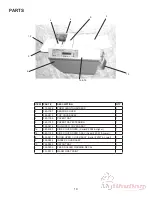
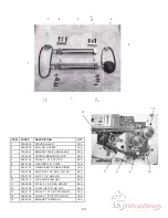
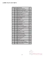
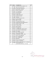
ITEM

PART #

DESCRIPTION

QTY

1

371-0076

BUSHING, FLANGE ALIGN 0.37

2

2

311-0106

LAST FORM DETECTIN SWITCH

1

3

360-1654

LAST FORM SWITCH BRACKET

1

4

332-0129

ROLLER ROD FEED

1

5

332-0131

SKEW ADJUST SHAFT

1

6

350-0099

BLACK SOFT-COMPOUND FEED WHEEL

3

7

375-5915

THUMB SCREW PLASTIC CAP

1

8

360-1643

RETAINER BRACKET

1

9

316-0011

STATIC WAND

1

10

360-1685

PAPER RAMP GUIDE

1

11

360-1686

CROSS MEMBER REAR

1

12

360-1687

CROSS MEMBER FRONT

1

13

360-1786

SIDE PAPER GUIDE

2

14

360-1655

SIDE GUIDE BRACKET MOUNT

2

15

375-0123

SIDE GUIDE, ADJUSTMENT SCREW

2

16

352-0009

CORK PAD WITH GLUE

1

-

352-0009A

CORK PAD WITHOUT GLUE

17

310-0134

PHOTO SENSOR HARNESS

1

18

360-1700

BRACKET. SENSOR

1

19

360-1729

SKEW PIVOT BRACKET

1

20

330-0090

COLLAR 250

1

21

377-0057

CURVED WASHER

2

22

374-0100

SOC HD. SCREW ¼-28 X 2 ¼

1

23

372-6575

THUMB SCREW CAP BLACK

1

24

332-0121

BRACE SHAFT

2

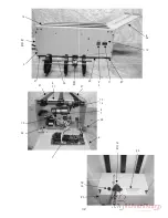
19

20

21

22

23

1

16

27

13

14

15

2

3

5

7

8

10

12

11

9

17

18

26

24

25

4

Detail A

Detail A

28

20

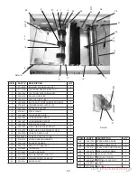
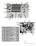
ITEM

PART #

DESCRIPTION

QTY

25

360-1790

FEEDER PAPER RAMP

1

26

360-1692

SEALER FRAME PLATE

2

27

375-0107

CENTER FEED TIRE SCREW

1

28

375-0110

SIDE COVER SCREWS

1

29

375-0070

6-32 X 1/4” SCREW

1

30

375-0044

SHOULDER SCREW

1

31

332-0132

FOLD PLATE SUPPORT

1

32

373-0027

SCREW

1

33

377-2809

WASHER

1

29

31

30

31

32

33

6

6

Summary of Contents for FD 2052

Page 1: ...Provided By http www MyBinding com http www MyBindingBlog com Formax FD2052 AutoSeal Service Manual...

Page 2: ...FD 2052 AutoSeal MAINTENANCE MANUAL FOURTH EDITION 12 2006...

Page 3: ...Adjusting The Gate Tip 7 Sealer Roller Clearance 7 Replacing Infeed Rollers 7 Replacing Singulator Pad 8 Replacing Cork Pad 8 Replacing Sealer Rollers 9 Replacing Folder Rollers 9 Belt Adjustment and...

Page 4: ...60 Hz 3 5 amps FE Model 240 volts 50 Hz 3 5 amps UNPACKING AND SETUP 1 Check package for shipping damage If there is shipping damage do not discard the box 2 CAUTION Two people must lift the machine o...

Page 5: ...llows one form to be folded Counter Reset Resets counter and resets faults Display Screen Displays all current functions Standard Fold Menu The Standard Folds Menu consists of three folds they are Let...

Page 6: ...h of panel A b Measure the length of panel B c Enter these measurements according to the instructions below 1 Measuring Fold Lengths Panel A Panel B Panel A Panel B Custom fold Programming prior to ch...

Page 7: ...and B to the desired fold location 7 Once the desired fold length has been correctly programmed it is necessary to hold down the appropriate Custom 1 9 button that s being used for 3 seconds to save...

Page 8: ...Autobatch mode press the Batch Count button and select AUTOBATCH by pressing the button Fig 3a 2 Once you have entered the Autobatch mode press the or button and Sheets Fig 3c will blink Press the or...

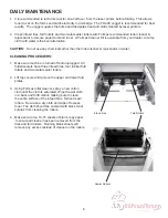
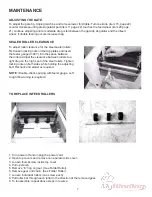
Page 9: ...r rejuvenator or water 1 Make sure machine is turned off and unplugged All folder sealers have three infeed tires four rubber fold rollers and two metal sealer rollers 2 Lift top covers and remove the...

Page 10: ...the power cord 2 Open top covers and remove non operator side cover 3 Loosen thumbscrew inside top cover 4 Pull up clamp 5 Remove E ring on gear See Folder Roller 6 Remove gear and chain See Folder R...

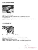
Page 11: ...lator pad to singulator mount let sit for at least ve minutes before reinstalling in feed rollers 6 Reinstall in feed rollers Singulator Pad 1 Lower in feed tray 2 Remove old cork pad a screwdriver or...

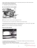
Page 12: ...two springs 8 To remove second roller tilt stainless steel center away from roller 9 Remove second roller the same way as the rst roller 10 To reassemble repeat above steps in reverse 11 Adjust belt...

Page 13: ...to remove To adjust belt rst determine if belt is too tight or too loose belt should have no more than 5 16 play Tighten or loosen the screw on the side of lever See arrow in above picture NOTE Be sur...

Page 14: ...e infeed clutch simultaneously press and hold the Test button and manually turn the infeed rollers in the overhand direction If the rollers lock the clutch is working properly 3 Fold Table Offset Adju...

Page 15: ...t values Plus button Custom increments the offset value for the selected fold table Minus button Custom decrements the offset value for the selected fold table Table A B button press and hold from Con...

Page 16: ...the arrow button has to be held down to advance as a test will be performed on the Batch Count button rst 3 Speed Pot Test This mode is used to verify the speed percentage 1 Check Speed Pot No Yes Sp...

Page 17: ...ff 6 After the check has been performed press the Batch Count green arrow key to advance to the next test 8 Motor Test This mode is used to verify that the motor is working properly 1 Check Motor No Y...

Page 18: ...tom Folds green arrow to select Table A or Table B Table A Top and Table B Bot use the Batch Count or buttons to set the offset up or down 5 Then Press the Test button to verify the settings Note If T...

Page 19: ...e the jammed form and reinstall and plug in the upper fold table close the top cover then press the counter reset button on the control panel to clear the fault signal WARNING Put the jam clearing han...

Page 20: ...e photo eyes The rst set of lights on the left is used to adjust the photo eye sensitivity for the fault detection There are three lights to help you do this The rst light is red low signal The second...

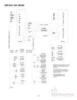
Page 21: ...WIRING DIAGRAM 18...

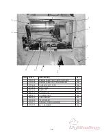
Page 22: ...APER TRAY EXTENSION 1 6 395 0816 NON OPER COVER ASSY 1 7a 360 2000 SIDE COVER OPER Serial 2098 Higher 1 7b 360 1789 SIDE COVER OPER ASSY Serial 2097 Lower 1 8 395 0817 DOOR OPER COVER ASSY Serial 2097...

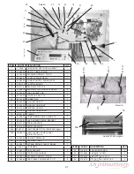
Page 23: ...MENT SCREW 2 16 352 0009 CORK PAD WITH GLUE 1 352 0009A CORK PAD WITHOUT GLUE 17 310 0134 PHOTO SENSOR HARNESS 1 18 360 1700 BRACKET SENSOR 1 19 360 1729 SKEW PIVOT BRACKET 1 20 330 0090 COLLAR 250 1...

Page 24: ...STO 1 17 360 1694 LOAD HANDLE SPRING BRACKET 1 18 360 1750 SPRING BRACKET 1 19 360 1645 SPRING BRACKET 1 20a 332 0141 JAM CLEARING TOOL S N 2098 Higher 1 20b 395 0813 JAM CLEARING HANDLE ASSY S N 2097...

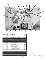
Page 25: ...78 PULLEY 3 8 PITCH 28LO50 1EA 9 310 0170 FOLD PLATE CABLE 2EA 10 372 6544 NON SWIVEL ADJUST GUIDE 4EA 11 319 0213 PROXIMITY SENSOR 3EA 12 365 0163 TIMING PULLEY 9T X LO37 Y380 1EA 13 379 0014 3 8 E T...

Page 26: ...AR BELT 210 L050 1EA 7 365 0179 TIMING BELT DOUBLE SIDED 1EA 8 375 0102 BOLT 3 8X1 1 4 SOC HD SC 4EA 9 375 0103 3 8 X 1 1 4 HEX HD 2EA 10 378 0118 3 8 40 HEX JAM NUT 2EA 11 374 0096 10 32 X 1 00 SOC H...

Page 27: ...PRING BRACKET 6EA 8 370 0025 ROLLER BEARING 7EA 9 370 0026 BEARING ROLLER DOUBLE SEAL 1EA 10 379 1073 3 8 RET RING TRUARC 4EA 11 360 1638 ROLLER SIDE BRACKET 2EA 12 360 1661 BEARING BRACKET 1EA 13 367...

Page 28: ...Y POWER BOARD 1EA 3 313 0004 COOLING FAN 110 VAC 1EA 4 341 0006 FAN GUARD 1EA 5 360 1490 FAN DUCT 1EA 6 360 1674 BOTTOM PAN 1EA 7 395 0910 POWER BOARD 1EA 8 395 0940 LOGIC BOARD 1EA 9 313 0049 1 3 HP...

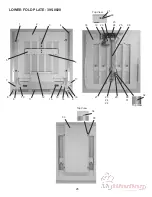
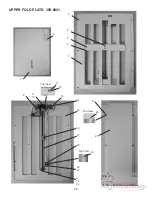
Page 29: ...26 LOWER FOLD PLATE 395 0820 1 17 16 8 15 14 10 13 12 11 10 9 8 7 5 6 4 3 2 Top View 35 34 33 Top View 18 27 26 25 22 21 23 24 20 19 23 24 28 Top View 30 31 29 32...

Page 30: ...5 342 0085 TORSION SPRING 1EA 16 360 1821 DIVERTER STOP 17 375 5436 6 32 X 3 16 FLAT HD SC 2EA 18 360 1772 LOWER CHUTE BOTTOM PLATE 1EA 19 375 5979 SCREW 4 40 X 3 16 UNDER CUT FLAT HD 1EA 20 395 0824...

Page 31: ...28 12 11 Top View Top View 18 Top View 24 25 23 14 19 16 17 20 21 9 10 22 8 1 7 6 5 4 3 2 UPPER FOLD PLATE 395 0821 13 9 10 15...

Page 32: ...EA 11 373 0111 ALLEN SCREW 2EA 12 377 1087 WASHER 2EA 13 375 5979 SCREW 4 40 X 3 16 UNDER CUT FLAT HD 1EA 14 395 0827 UPPER PLATE HARNESS 1EA 15 360 1768 UPPER SHEET BOTTOM PLATE 1EA 16 334 0363 LEAD...

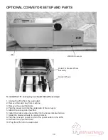
Page 33: ...g the power cord into the underside of the conveyor 5 Attach the conveyor to the 2052 6 Install the stacker wheel assembly into the holes indicated above 7 Adjust the stacker wheels to conveyor decal...

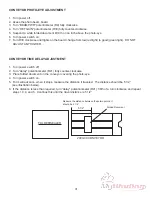
Page 34: ...R TIME DELAY ADJUSTMENT 1 Turn power switch off 2 Turn delay potentionmeter R41 fully counter clockwise 3 Place folded document on the conveyor covering the photo eye 4 Turn power switch on 5 Form wil...

Page 35: ...32 16 17 34 24 10 4 28 6 7 13 14 5 26 33 35 15 27 25 29 22 2 3 11 27 12 8 32 23 21 9 31 21 18 19 20 30 1...

Page 36: ...Y 1 16 319 0096 RECEPTACLE RECESSED POWER 1 17 310 0039 POWER SUPPLY CORD 1 18 317 0006 FUSE HOLDER 1 19 317 0013 1 5A 3AG FUSE 1 20 360 1765 BOTTOM PAN 1 21 369 0018 CARRIER BELT 3 22 325 0152 CAUTIO...

Page 37: ......

Page 38: ......
Reviews: