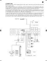
EN
- 6 -
13.-
100 V zone output terminals (COM - Z1 - Z2 - Z3 - Z4):
terminals for connecting the speaker lines for
zones 1 to 4. To activate/deactivate the zones, use the front switches. The zone selection terminals
must only be used with loudspeakers with 100 V line transformer. The total power connected in the
loudspeakers must not exceed the amplifier power. Connect the positive from each zone to the
corresponding Z1 to Z4 terminal and the common from all zones to a COM terminal.
14.-
LEVEL/MOH:
monitor output volume control. Turn the control clockwise to increase volume and
anticlockwise to decrease it.
15.-
Output terminals for auxiliary speaker 1 W 8 Ω - 600 Ω (Monitor):
o utput terminals for connecting
an external loudspeaker as a monitor. A 1 W internal amplifier is available. It only monitors the AUX IN
input, controlled by the AUX volume, and its level is adjustable using the LEVEL/MOH control on the
back panel.
16.-
TEL. INPUT:
telephone input terminals. For connecting to a telephone switchboard for paging from the
switchboard with priority over the rest of the inputs. See the switchboard characteristics to adjust them
to the amplifier input level. The signal level can be adjusted using the TEL. LEVEL control on the back
panel.
Note
: the amplifier is supplied with priority deactivated. To activate this function you must turn the
MUTE/SEN control clockwise, to its maximum (maximum priority).
17.-
TEL. LEVEL:
TEL. INPUT volume control. For adjusting the volume from the telephone switchboard that
is connected to the TEL. INPUT terminals. Turning the control clockwise the volume increases and anti-
clockwise it decreases.
MA-125Z_MANUAL_(EN)_20170824_Maquetación 1 24/8/17 10:23 Página 6
Summary of Contents for MA-125Z
Page 1: ...MA 125Z AMPLIFIER WITH ZONE SELECTOR INSTRUCTION MANUAL...
Page 8: ...EN 8 BLOCK DIAGRAM...
Page 11: ...11 EN...
Page 12: ...www fonestar com...


