


EN
- 4 -
DESCRIPTION
- P.A. amplifier.
- 4 selectable loudspeaker zones with independent volume control.
- Phantom power and priority.
CONTROLS AND FUNCTIONS
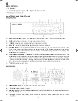
FRONT PANEL
1.-
INPUT 1-4 and AUX
: controls for adjusting the volume from inputs 1 to 4 and the auxiliary input.
2.-
BASS
: strengthens or weakens the bass frequencies ±10 dB.
3.-
TREBLE
: strengthens or weakens the treble frequencies ±10 dB.
4.-
MASTER
: control for adjusting the general output volume in all inputs.
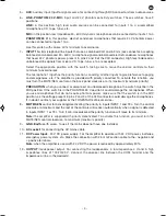
5.-
OUTPUT LEVEL
: output signal level LED indicators. For adjusting the individual volume controls in the
inputs or the volume control for the MASTER output so that the level does not exceed the green LED
indicators. The red LED indicators show saturation or a distorted signal, that could damage the
loudspeakers or the amplifier.
6.-
ZONE SELECTOR(ZONE 1 to ZONE 4)
: there are 4 individual zone controls and a general control. The
loudspeaker line from one zone can be connected or disconnected independently, by just pressing the
button for the corresponding zone (ZONE 1-ZONE 4). Turn the respective volume controls for each zone
clockwise to increase the volume and anti-clockwise to lower it. When the ALL button is pressed, the 4
zone controls work simultaneously and the output signal volume will be at its maximum.
7.-
POWER
: amplifier on/off switch.
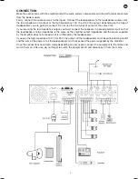
BACK PANEL
1.-
VENTILATION SLIT
: for ventilating the final step in the power.
2.-
115V/230V
: power voltage selector.
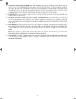
3.-
AMP IN/PRE OUT
: the connection bridge between the 2 RCA connectors communicates the PRE OUT
signal AMP IN input.
4.-
LINE OUT
: auxiliary line output. Signal output for recording, mixer, power amp, etc., 2 x RCA
connectors.
MA-125Z_MANUAL_(EN)_20170824_Maquetación 1 24/8/17 10:23 Página 4
Summary of Contents for MA-125Z
Page 1: ...MA 125Z AMPLIFIER WITH ZONE SELECTOR INSTRUCTION MANUAL...
Page 8: ...EN 8 BLOCK DIAGRAM...
Page 11: ...11 EN...
Page 12: ...www fonestar com...


