


4.1
C.H. OUTPUT REGULATION
When the boiler is fuelled with natural gas
(G20), it is possible to change the maxi-
mum pressure value according to the dia-
gram shown in fig. 13 in order to adjust
C.H. output to the thermal requirements of
the system.
If the pressures need to be corrected fol-
low the indications in section 4.3.1. In order
to avoid the variation of the minimum pres-
sure lock the adjusting screw (2 fig. 11/a).
4.2
GAS VALVE
(fig. 11)
The boilers are equipped standard with the
HONEYWELL VK 4105Q gas valve.
Gas pressure calibration is carried out by
SIME on the production line and foresees
the minimum C.H.output at 23,2 kW and
the maximum C.H.output at 31,0 kW.
If the pressures are checked only at the
burner, connect the pressure gauge as indi-
cated in fig. 12. If corrections are required
refer to section 4.3.1.
4.3
GAS CONVERSION
This operation must be performed by
authorised personnel using original Sime
components.
To convert from natural gas to LPG or vice
versa, perform the following operations:
– Close the gas cock.
– Replace the principal nozzles and the ø
10 aluminium washers included in kit
(use a 12 wrench in order to carry out
this operation).
–
At start-up change the starting pres-
sure (STEP) of the gas valve by posi-
tioning the index of the screw accord-
ing to the type of gas, as mentioned in
fig. 11.
– To set the values of maximum and mini-
mum gas pressure, follow the instruc-
tions given in section 4.3.1.
Seal the regulators after the operating
pressure values have been changed.
– After have ultimated the conversion of
the boiler, please stick onto the casing
panel the plate showing the relevant
feeding gas which is included into the kit.
NOTE: When reassembling components
which you have removed, replace gas
seals; test all gas connections after
assembly using soapy water or a product
made specifically for the purpose, being
sure not to use open flame.
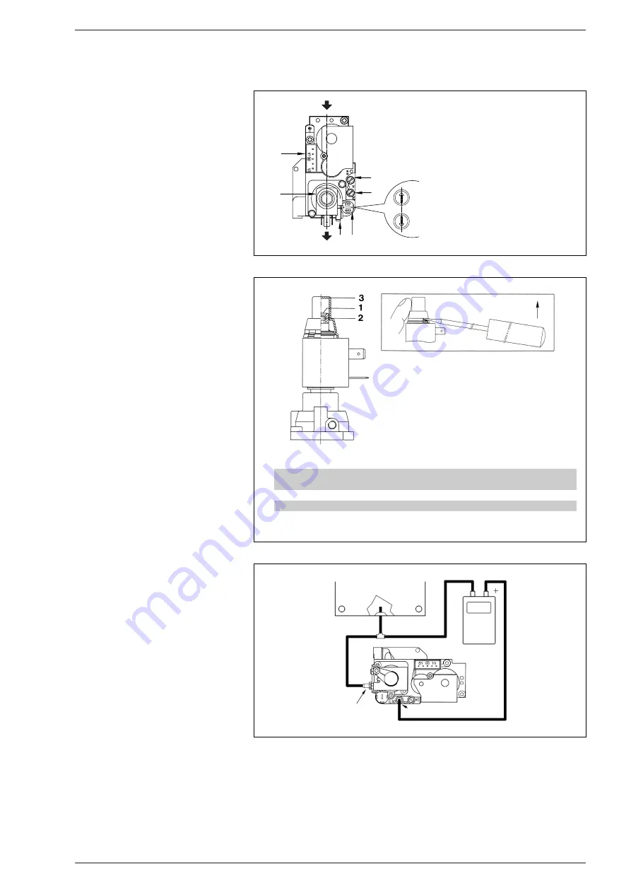
4.3.1
Adjusting valve pressures
For maximum and minimum pressure cali-
bration follow the procedure listed below
(fig. 11/a):
– Connect the column or a manometer to
the intake downstream of the gas valve
(4 fig. 11).
–
Disconnect the valve VENT pressure test
point tube (5 fig. 11).
– Remove the cap (3) from the modulator.
– Place the boiler stat knob at the maxi-
mum position.
– Turn on the boiler.
– Remember that rotating clockwise will
increase pressure while rotating anti-
clockwise will diminish it.
– Check the gas inlet pressure at the rele-
vant pressure test point (3 fig. 11) with
the boiler running at the maximum output.
– Regulate the maximum pressure by turn-
ing the nut with a fixed wrench (1)
searching for the maximum pressure
Table 3
, or, for the natural gas (G20), if
44
4
USE AND MAINTENANCE
KEY
1
Maximum pressure adjusting nut
2
Minimum pressure adjusting screw
3
Plastic cap
Fig. 11/a
2
1
3
5
4
6
G20
G30-G31
Fig. 11
KEY
1
Modulator
2
EV1-EV2 coils
3
Pressure inlet upstream
4
Pressure inlet downstream
5
VENT pressure test point
6
STEP
Fig. 12
TABLE 3
Type of gas
Burner max. pressure
Burner min. pressure
mbar
mbar
Methane (G20)
12,0
7,1
Butane (G30)
28,1
17,8
Propane (G31)
35,9
17,8
SEALED CHAMBER
VENT PRESSURE TEST POINT
PRESSURE INLET DOWNSTREAM
MANOMETER


