FOLKSWAGEN Golf 2015 Repair Manual Download Page 66

Pro

te

c

t

ed

  b

y

  co

p

y

rig

h

t. 

C

o

p

y

in

g

  fo

pr

iv

a

t

e

 o

r

 c

o

m

m

e

r

c

ia

p

u

rp

o

s

e

s

,

 i

n

 p

a

rt

o

r i

n

 w

h

o

le

is

 n

o

t

 p

e

r

m

it

t

e

d

 u

n

l

e

s

s

 a

ut

ho

r

i

s

ed

 b

y

 V

olk

sw

a

ge

n AG

.


V

olk

s

w

a

g

en

 AG do

es 

n

ot g

uar

ante

e

 or a

c

c

ep

t

 a

ny


li

a

b

i

li

t

y

 w

ith

 r

e

s

p

e

c

t

 t

o


th

e

 c

o

rr

e

c

t

n

e

s

s


o

f

in

fo

r

m

a

tio

n

 in

 th

is

 d

o

c

um

en

t.

C

o

py

rig

ht b

y


V

olk

sw

a

ge

n


A

G.

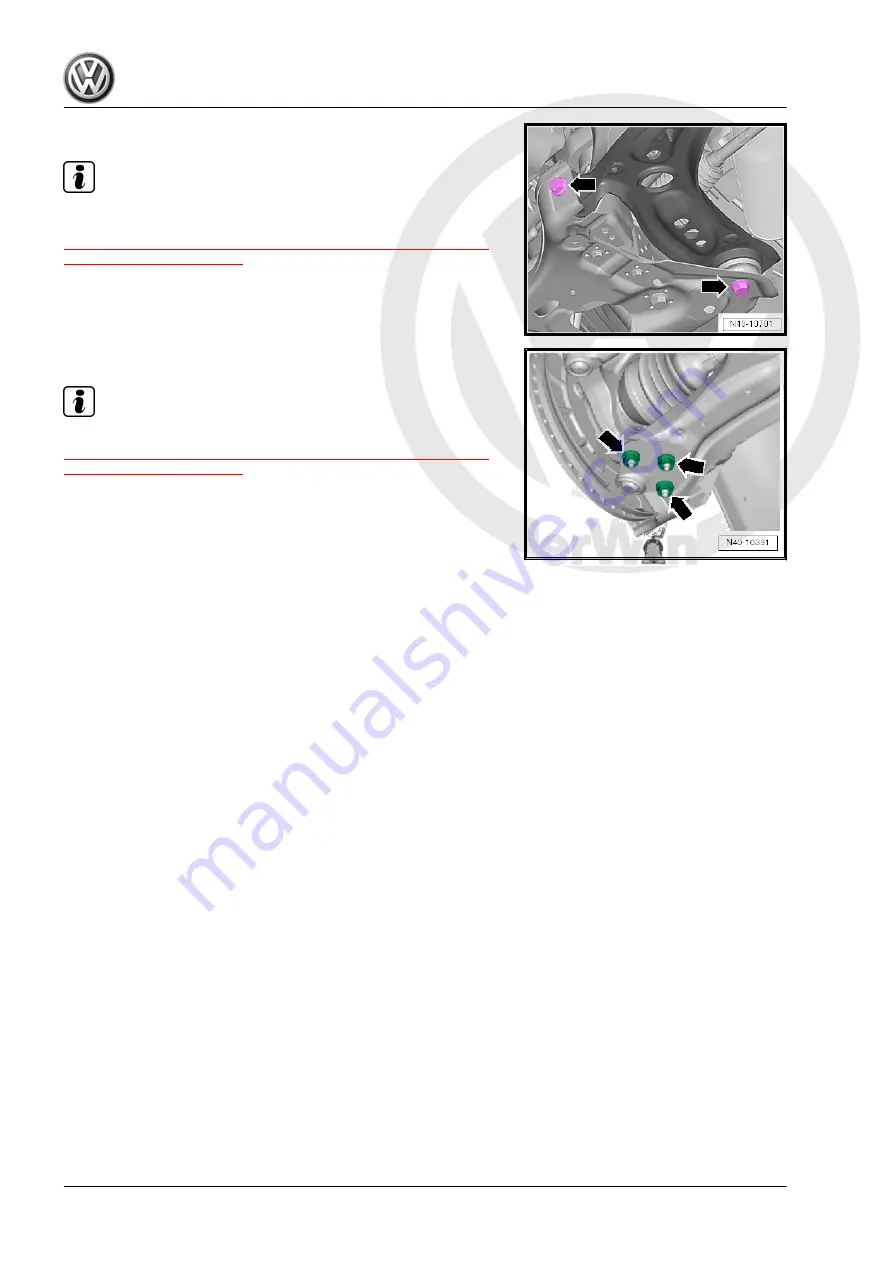
– Tighten the screws -arrows-.

Note

Tighten the bolts -arrows- and nuts in curb weight position. Refer

to

⇒ “3.8.1 Wheel Bearing in Curb Weight, Lifting Vehicles with Coil

Spring, Front Axle”, page 6

 .

– Tighten nuts -arrows-.

Note

Tighten the nuts -arrows- in curb weight position. Refer to

⇒ “3.8.1 Wheel Bearing in Curb Weight, Lifting Vehicles with Coil

Spring, Front Axle”, page 6

 .

– Remove the -T10533- .
– Remove the exhaust system double clamp. Refer to ⇒  Rep.

Gr.  26 ; Exhaust Pipes/Mufflers; Exhaust Pipes/Mufflers, Sep‐

arating .

– Install the pendulum support. Refer to ⇒  Rep. Gr.  10 ; Sub‐

frame Mount; Pendulum Support, Removing and Installing .

Golf 2015 ➤ , Golf Variant 2015 ➤

Suspension, Wheels, Steering - Edition 03.2016

60

     Rep. Gr.40 - Front Suspension

Summary of Contents for Golf 2015

Page 1: ... ssauthorisedbyVolkswagenAG VolkswagenAGdoesnot guaranteeorac c e p t a n y l i a b i l i t y w i t h r e s p e c t t o t h e c o r r e c t n e s s o f i n f o r m a t i o n i n t h i s d o c u m e n t C o p y r i g h t b y V o l k s w a g e n A G Repair Manual Golf 2015 Golf Variant 2015 Suspension Wheels Steering Edition 03 2016 Service Service Department Technical Information ...

Page 2: ...st of Workshop Manual Repair Groups Repair Group 00 Technical Data 40 Front Suspension 42 Rear Suspension 43 Level Control System 44 Wheels Tires and Vehicle Alignment 48 Steering Technical information should always be available to the foremen and mechanics because their careful and constant adherence to the instructions is essential to ensure vehicle road worthiness and safety In addition the nor...

Page 3: ...14 40 Front Suspension 15 1 Front Axle 15 1 1 Overview Front Axle 15 2 Subframe 16 2 1 Overview Subframe 16 2 2 Subframe Securing 17 2 3 Subframe Lowering 20 2 4 Subframe without Steering Gear Removing and Installing 23 2 5 Subframe with Steering Gear Removing and Installing 27 2 6 Subframe Servicing 32 2 7 Stabilizer Bar Removing and Installing 38 2 8 Coupling Rod Removing and Installing 42 2 9 T...

Page 4: ...r Removing and Installing 178 4 3 Coupling Rod Removing and Installing 179 5 Control Arm Tie Rod 181 5 1 Overview Transverse Link 181 5 2 Overview Tie Rod 184 5 3 Upper Transverse Link Removing and Installing 185 5 4 Lower Transverse Link Removing and Installing 187 5 5 Tie Rod Removing and Installing 189 6 Suspension Strut Shock Absorber Spring 191 6 1 Overview Suspension Strut Shock Absorber and...

Page 5: ...g 287 1 5 Wheel Changing 288 1 6 Tire Sealant Disposing 292 1 7 Vehicles with Tire Mobility Kit 292 2 Tire Pressure Monitoring System 294 2 1 Tire Pressure Monitoring System Description 294 3 Vehicle Alignment 296 3 1 Axle Alignment Information 296 3 2 Test Prerequisites 296 3 3 Measurement Preparations 297 3 4 Axle Alignment Specified Values 298 3 5 Axle Alignment Procedure 302 3 6 Evaluating Nee...

Page 6: ...Overview Steering Column 338 2 2 Steering Column Checking for Damage 339 2 3 Steering Column Handling and Transporting 339 2 4 Steering Column Removing and Installing 340 2 5 Electronic Steering Column Lock Control Module J764 Removing and Installing 348 3 Steering Gear 350 3 1 Overview Steering Gear 350 3 2 Steering Gear Removing and Installing 351 3 3 Boot Removing and Installing 357 3 4 Tie Rod...

Page 7: ...al inspection for faulty boots and grease boots Check electric and hydraulic lines and hoses for chafe marks cuts and kinks Check of hydraulic lines threaded connections and steering gear for proper seal Make sure the steering gear and lines are securely fastened Check proper function through entire steering angle by turning steering wheel from stop to stop Steering wheel must be ro tary without h...

Page 8: ...tes can be found in re spective repair manuals ELSA Checking of accident vehicles described here refers to suspen sion and does not lay claim to completeness for entire vehicle Electronic Vehicle Systems Safety related systems such as ABS EDS Airbag electronically controlled suspension systems electromechanical electrohy draulic steering and other driver assist systems must be checked for possible...

Page 9: ... to the engine automatically starting on vehi cles with a Start Stop system For vehicles with an active start stop system the engine can automatically start if necessary Make sure the start stop system is off whenever working on the vehicle Turn off the ignition and turn it back on only when necessary 2 2 Subframe Safety Precautions Welding and straightening work on supporting or wheel car rying c...

Page 10: ...t stand and on the vehicle have shown that the replacement of a large number of rejected shock absorbers was not justified Slight leaking of oil sweating at piston rod seal is no reason to replace a shock absorber A shock absorber damp with oil is OK under the following circumstances Oil leakage shaded in illustration is visible but dull matte and possibly dry due to dust Oil excretion extends fro...

Page 11: ...Note If this is not the case the shock absorber must be replaced As long as there is no large loss of oil the mode of operation corresponds to that of a conventional shock absorber The damping function is also completely available without gas pressure as long as there is no large loss of oil However noise may increase 3 4 Steering Gear To perform a problem free and successful steering gear repair ...

Page 12: ...sitive parts in diagonal manner in stages for example servo motor with control module Tightening specifications for non lubricated bolts and nuts are given Always replace self locking nuts and bolts 3 7 Electrical Components Surely everyone has been shocked at one time or another when coming into contact with a metal object The reason for this is the build up of static electricity in the human bod...

Page 13: ...ed range of motion Axle components with bonded rubber bushings must be brought into the position they will be in during driving before tightening curb weight position Otherwise the bonded rubber bushing will be stressed result ing in a shortened service life By raising appropriate suspension using Engine and Gearbox Jack VAS6931 and Engine Gearbox Jack Adapter Wheel Hub Support T10149 this positio...

Page 14: ... GM1 A8H G06 2UC GM3 A8G G06 2UJ G04 2UM G29 368 10 mm GTI heavy duty suspension G06 2UN 383 10 mm 1 The suspension that the vehicle is equipped with is indicated on the vehicle data plate The suspension is indicated by a PR number Allocation of the PR number according to the suspen sion Lift the wheel bearing housing using the Engine and Gearbox Jack VAS6931 until dimension a is reached WARNING D...

Page 15: ...shings must be brought into the position they will be in during driving before tightening curb weight position Otherwise the bonded rubber bushing will be stressed result ing in a shortened service life By raising the axle on one side using the Engine and Gearbox Jack VAS6931 and Engine Gearbox Jack Adapter Wheel Hub Support T10149 this position can be simulated on the hoist Note Before lifting th...

Page 16: ...385 10 mm Sport G01 G02 G07 2UC G21 370 10 mm Raised G01 G02 2UF 400 10 mm DCC G03 375 10 mm GTI G06 2UC G06 2UJ G04 2UM 370 10 mm GTI heavy duty suspension G06 2UN 385 10 mm 1 The suspension that the vehicle is equipped with is indicated on the vehicle data plate The suspension is indicated by a PR number Allocation of the PR number according to the suspen sion Lift the wheel bearing housing usin...

Page 17: ...nting and Emptying Standard Shock Absorber page 11 4 1 2 Front Shock Absorbers Venting and Emptying DCC Shock Absorber page 12 4 1 1 Front Shock Absorbers Venting and Emptying Standard Shock Absorber Secure the gas filled shock absorber vertically in vise with piston rod facing down WARNING Wear protective eyewear while drilling Drill a 3 mm hole A through the shock absorber outer tube Note Gas es...

Page 18: ...es Hold the shock absorber over an appropriate container for catching oil and move the piston rod repeatedly through the entire stroke until no more oil flows out 4 2 Rear Shock Absorbers Venting and Emptying 4 2 1 Rear Shock Absorbers Venting and Emptying Standard Shock Absorber page 12 4 2 2 Rear Shock Absorbers Venting and Emptying DCC Shock Absorber page 13 4 2 1 Rear Shock Absorbers Venting a...

Page 19: ...orbers Venting and Emptying DCC Shock Absorber Tension the gas filled shock absorber vertically in the vise WARNING Wear protective eyewear while drilling Drill a 3 mm hole A through the shock absorber outer tube Note Gas escapes when drilling Continue drilling until the tube inside is drilled through ap proximately 25 mm deep Drill a second 6 mm hole B through the outer and inner shock absorber t...

Page 20: ... a n y l i a b i l i t y w i t h r e s p e c t t o t h e c o r r e c t n e s s o f i n f o r m a t i o n i n t h i s d o c u m e n t C o p y r i g h t b y V o l k s w a g e n A G 5 Special Tools Special tools and workshop equipment required Engine and Gearbox Jack VAS6931 Tensioning Strap T10038 Engine Gearbox Jack Adapter Wheel Hub Sup port T10149 Golf 2015 Golf Variant 2015 Suspension Wheels Ste...

Page 21: ... t t o t h e c o r r e c t n e s s o f i n f o r m a t i o n i n t h i s d o c u m e n t C o p y r i g h t b y V o l k s w a g e n A G 40 Front Suspension 1 Front Axle 1 1 Overview Front Axle page 15 1 1 Overview Front Axle I Refer to 2 Subframe page 16 II Refer to 3 Suspension Strut and Up per Control Arm page 44 III Refer to 4 Lower Control Arm and Ball Joint page 54 IV Refer to 5 Wheel Bearing ...

Page 22: ...ge 38 2 8 Coupling Rod Removing and Installing page 42 2 9 Thread in Longitudinal Member Servicing page 43 2 1 Overview Subframe 1 Stabilizer Bar with the Rub ber Bushings Removing and instal ling Refer to 2 7 Stabilizer Bar Removing and Instal ling page 38 2 Nut 65 Nm Replace after removal Counterhold at socket head of joint bolt when tightening 3 Suspension Strut 4 Coupling Rod Removing and inst...

Page 23: ...placing Refer to 2 6 Subframe Servicing page 32 13 Upper Bonded Rubber Bushing for Pendulum Support Replacing Refer to 2 6 Subframe Servicing page 32 14 Nut 65 Nm Replace after removal Counterhold at socket head of joint bolt when tightening 2 2 Subframe Securing Special tools and workshop equipment required Assembly Tool Sub frame Alignment T10486A Four Locating Pins T10486 1 Locating Pins T10486...

Page 24: ... Sub frame Alignment T10486A If the Assem bly Tool Sub frame Alignment T10486A is already in the service operation then only the addition of the two Locating Pins T10486 1 is required If the Assembly Tool Sub frame Alignment T10486A is not already in the service operation then the Assembly Tool Sub frame Alignment T10486A is to be used It contains four Locating Pins T10486 1 and two Locating Pins ...

Page 25: ...a g e n A G To secure the subframe the Locating Pins T10486 1 must be installed at the positions 3 5 7 and 8 one after the other Note The Locating Pins T10486 1 may only be tightened to a maxi mum of 20 Nm since otherwise the locating pin threads will be damaged Secure the Rear Subframe Remove the bolts 1 Remove the bolt 3 and the support 4 Insert the Locating Pin T10486 1 1 and tighten to 20 Nm R...

Page 26: ...erse of installation noting the following Only remove one locating pin and replace this with a bolt For vehicles with a vehicle level sensor perform the basic set ting for the wheel damping electronics Refer to Vehicle Diag nostic Tester Tightening Specifications Refer to 2 1 Overview Subframe page 16 Refer to Engine Mechanical Fuel Injection and Ignition Rep Gr 10 Subframe Mount Overview Subframe...

Page 27: ...Bar Removing Turn the steering wheel to the straight ahead position and re move the ignition key so that the steering wheel lock engages Vehicle with Keyless Access Keyless Locking and Starting Sys tem Switch the ignition off and open the driver door so the steering wheel lock locks Remove the bolt 1 and fold the footwell trim panel 2 in di rection of arrow into the vehicle interior Remove the bol...

Page 28: ... e n t C o p y r i g h t b y V o l k s w a g e n A G Remove the exhaust system bracket from the subframe arrows Remove the pendulum support bolts 1 Remove the hex nut 1 from the right and left coupling rod 3 Remove the coupling rod 3 from the stabilizer bar 2 on the left and right sides Vehicles with a Vehicle Level Sensor Disconnect the connector 1 from the Left Front Level Control System Sensor ...

Page 29: ...e clean Remove the Locating Pins T10486 1 Refer to page 20 For vehicles with a vehicle level sensor perform the basic set ting for the wheel damping electronics Refer to Vehicle Diag nostic Tester Tightening Specifications Refer to 2 1 Overview Subframe page 16 Refer to 3 1 Overview Steering Gear page 350 Refer to 2 1 Overview Steering Column page 338 Refer to Engine Mechanical Fuel Injection and ...

Page 30: ...h t b y V o l k s w a g e n A G Removing Note Subframe is removed together with control arms Loosen the wheel bolts Raise the vehicle Remove the wheels Remove the lower noise insulation Refer to Body Exterior Rep Gr 66 Noise Insulation Overview Noise Insulation Remove the exhaust system bracket from the subframe arrows Remove the pendulum support bolts 1 Remove the hex nut 1 from the right and lef...

Page 31: ...e n t C o p y r i g h t b y V o l k s w a g e n A G Remove the nuts arrows on the left and right side of the ve hicle Vehicles with Level Control System Sensor Disconnect the connector 1 from the Left Front Level Control System Sensor G78 or Right Front Level Control Sensor G289 Continuation for all Vehicles Remove the clips 1 and 2 for the wiring harness 3 from the subframe and the steering gear ...

Page 32: ... o r m a t i o n i n t h i s d o c u m e n t C o p y r i g h t b y V o l k s w a g e n A G Place the VAS6931 1 under the subframe Secure the subframe refer to 2 2 Subframe Securing page 17 and lower it approxi mately 10 cm Remove the expanding clip arrow Lower the subframe using the VAS6931 Secure the subframe on the VAS6931 Secure the steering gear on the body Installing Install in reverse order ...

Page 33: ...lts Refer to Rep Gr 10 Subframe Mount Overview Subframe Mount Noise insulation bolts Refer to Body Exterior Rep Gr 66 Noise Insulation Overview Noise Insulation Exhaust system to subframe Refer to Rep Gr 26 Exhaust Pipes Mufflers Overview Muffler If the steering wheel is still crooked after using the T10486 1 then an axle alignment is necessary In this case the record it in the vehicles axle align...

Page 34: ...rsal joint in direction of arrow Caution If the universal joint is separated from the steering gear the following work cannot be performed Connect the battery Switching on the ignition Turning the steering gear Turning the steering column These points must be observed since performing these actions could cause irreparable damage Loosen the wheel bolts Raise the vehicle Remove the wheels Remove the...

Page 35: ...g rod 3 Remove the coupling rod 3 from the stabilizer bar 2 on the left and right sides Remove the nuts arrows on the left and right side of the ve hicle Remove the control arm from the ball joint Loosen the nut from the tie rod end but do not unscrew yet Caution To protect the thread screw the nut on the pin a few turns Remove the tie rod end from the wheel bearing housing and remove the nut 1 T1...

Page 36: ...the connector 2 from the After Run Coolant Pump V51 To do so open the catch 3 in the direction of the arrow and release the connector Remove the clips 1 and 2 for the wiring harness 3 from the subframe and the steering gear Place the VAS6931 1 under the subframe Secure the subframe refer to 2 2 Subframe Securing page 17 and lower it approxi mately 10 cm Remove the bolts arrows and remove the heat ...

Page 37: ... e c t n e s s o f i n f o r m a t i o n i n t h i s d o c u m e n t C o p y r i g h t b y V o l k s w a g e n A G Disconnect the connectors 1 and 2 from the steering gear Unclip the wiring harness 1 from the steering gear 2 arrows Remove the expanding clip arrow Lower the subframe using the VAS6931 Secure the subframe to the VAS6931 with the accompanying strap Installing Install in reverse order ...

Page 38: ...erform the basic setting for the wheel damping electronics using the Ve hicle Diagnostic Tester Tightening Specifications Refer to 2 1 Overview Subframe page 16 Refer to 5 1 Overview Wheel Bearing page 70 Refer to 3 1 Overview Steering Gear page 350 Refer to 2 1 Overview Steering Column page 338 Pendulum support bolts Refer to Rep Gr 10 Subframe Mount Overview Subframe Mount Noise insulation bolts...

Page 39: ...place the Pendulum Support Bonded Rubber Bushing Remove the front noise insulation Refer to Body Exterior Rep Gr 66 Noise Insulation Overview Noise Insulation Remove the hex nut 1 from the right and left coupling rod 3 Remove the coupling rod 3 from the stabilizer bar 2 on the left and right sides Remove the stabilizer bar bolts 1 Leave the stabilizer bar in the installed position on the vehicle R...

Page 40: ... t y w i t h r e s p e c t t o t h e c o r r e c t n e s s o f i n f o r m a t i o n i n t h i s d o c u m e n t C o p y r i g h t b y V o l k s w a g e n A G 1 Thrust Piece VAS6779 1 2 Tube VAS6779 4 3 Thrust Piece VAS6779 5 4 Hydraulic Press VAS6178 with Bearing Installer Wheel Hub Bearing Kit Pressure Head T10205 13 5 Hexagon Nut VAS6779 3 6 Threaded Rod VAS6779 2 Golf 2015 Golf Variant 2015 Su...

Page 41: ...for the pendulum support arrow in the subframe Using a chisel or similar tool 1 make a break in the upper bonded rubber bushing 2 outer race Note This work sequence is necessary to prevent tilting of the bonded rubber bushing outer race in the area of the pendulum support opening in the subframe Completely press out both bonded rubber bushings at the same time Prepare the Bonded Rubber Bushing Bef...

Page 42: ... Use VW412 2 Thrust Piece VAS6779 5 the side with the letter A points up 3 Bonded rubber bushing 4 Funnel VAS6779 6 5 Tube VAS6779 4 6 Press Plate VW401 Insert the Counter Hold VAS6779 7 1 into the subframe Insert the Insert VAS6779 7 1A 2 in the pendulum support opening in the subframe Fasten the Insert VAS6779 7 1A onto the Counter Hold VAS6779 7 1 Make sure that the Insert VAS6779 7 1A 2 is sea...

Page 43: ...9 9 4 Incremental Ring VAS6779 8 the marking I on the Incre mental Ring VAS6779 8 must align with the marking X on the Thrust Piece VAS6779 9 5 Hydraulic Press VAS6178 with Bearing Installer Wheel Hub Bearing Kit Pressure Head T10205 13 6 Hexagon Nut VAS6779 3 7 Threaded Rod VAS6779 2 Press in both bonded rubber bushing at the same time Remove Hydraulic Press Bushing Tool Kit VAS6779 from the subf...

Page 44: ...ifications Refer to 2 1 Overview Subframe page 16 Refer to Engine Mechanical Fuel Injection and Ignition Rep Gr 10 Subframe Mount Overview Subframe Mount or Engine Mechanical Fuel Injection and Glow Plug Rep Gr 10 Subframe Mount Overview Subframe Mount Refer to Body Exterior Rep Gr 66 Noise Insulation Overview Noise Insulation 2 7 Stabilizer Bar Removing and Installing Special tools and workshop e...

Page 45: ...a g e n A G Remove the hex nut 1 from the right and left coupling rod 3 Remove the coupling rod 3 from the stabilizer bar 2 on the left and right sides Remove the nuts arrows on the left and right side of the ve hicle Vehicles with Level Control System Sensor Disconnect the connector 1 from the Left Front Level Control System Sensor G78 or Right Front Level Control Sensor G289 Remove the nut 1 Rem...

Page 46: ... t i o n i n t h i s d o c u m e n t C o p y r i g h t b y V o l k s w a g e n A G Remove the bolt 1 Remove the Left Front Level Control System Sensor G78 2 or Right Front Level Control Sensor G289 Continuation for all Vehicles Remove the clips 1 and 2 for the wiring harness 3 from the subframe and the steering gear Remove the stabilizer bar bolts 1 Remove the steering gear bolts 1 Pry the steerin...

Page 47: ... e s s o f i n f o r m a t i o n i n t h i s d o c u m e n t C o p y r i g h t b y V o l k s w a g e n A G Place the VAS6931 1 under the subframe Secure the subframe refer to 2 2 Subframe Securing page 17 and lower it approxi mately 10 cm Remove the expanding clip arrow Lower the subframe with the VAS6931 until the stabilizer bar can be removed toward the rear Installing Install in reverse order o...

Page 48: ...g electronics using the Vehicle diagnostic tester Tightening Specifications Refer to 2 1 Overview Subframe page 16 Refer to 2 1 Overview Steering Column page 338 Refer to 2 1 Overview Front Level Control System Sensor page 277 Pendulum support bolts Refer to Rep Gr 10 Subframe Mount Overview Subframe Mount Noise insulation bolts Refer to Body Exterior Rep Gr 66 Noise Insulation Overview Noise Insu...

Page 49: ...d 1 from the sus pension strut Remove the hex nut 1 from the coupling rod 3 Remove the coupling rod 3 from the stabilizer bar 2 Installing Install in reverse order of removal Note the following Tighten the coupling rod nuts on the suspension strut or sta bilizer bar counterholding on the multipoint socket head if necessary Tightening Specifications Refer to 2 1 Overview Subframe page 16 2 9 Thread...

Page 50: ... Arm 1 Spring Seat Note the installation po sition 2 Shock Absorber Different versions Re fer to the Parts Catalog 3 Bolt 70 Nm 180 Replace after removal The bolt tip must face in direction of travel 4 Wheel Bearing Housing Different versions Re fer to the Parts Catalog 5 Nut Replace after removal 6 Protective Sleeve Different versions Re fer to the Parts Catalog 7 Coil Spring Removing and instal ...

Page 51: ...o 6 4 Drive Axle Threaded Connection Loosening and Tight ening page 101 Caution The wheel bearing must not be under load when the drive axle threaded connection on the wheel side is loose If the wheel bearings are under the load of the vehicle weight the wheel bearing will be damaged This reduces the service life of the wheel bearings The drive axle bolt may be loosened maximum 90 when the vehicle...

Page 52: ... Level Control System Sensor G78 or Right Front Level Control Sensor G289 from the control arm 3 Continuation for all Vehicles Remove the nuts arrows Remove the wheel bearing housing with the ball joint from the control arm Remove the drive axle outer joint from the wheel hub If the drive axle cannot be pulled out of the wheel bearing then the drive axle can be pushed out of the wheel bearing usin...

Page 53: ...ition so that the hydraulic operation can be used Secure the drive axle to the body using wire Caution The drive axle must not hang down otherwise the inner joint will be damaged by over bending Vehicles with Adaptive Chassis DCC Disconnect the connector 1 from the shock absorber 2 Note If there is moisture in the connector area blow compressed air on the contacts on the shock absorber and the con...

Page 54: ... the suspension strut metal retainer is not damaged Turn the ratchet 90 and remove it from the 3424 Press the brake rotor toward the suspension strut by hand Otherwise the shock absorber tube could tilt in the wheel bearing housing hole Lower the wheel bearing housing 1 using the VAS6931 in the direction of the arrow Lower the wheel bearing housing 1 so that the shock ab sorber tube hangs freely a...

Page 55: ...C o p y r i g h t b y V o l k s w a g e n A G Remove the bolts 1 for upper strut mount and remove shock absorber mount Installing Position the suspension strut so that the arrows 1 are always inside One of the two arrows 1 on the spring plate 2 must point in the direction of travel Insert the suspension strut and fasten the bolts 1 to the body Place the VAS6931 under the T10149 and secure the whee...

Page 56: ... joint from the control arm Lower the wheel bearing housing 1 using the VAS6931 in the direction of the arrow Push the wheel bearing housing with the VAS6931 upward and install it on the suspension strut at the same time Re bolt the ball joint to the control arm and push the wheel bearing housing upward again until the end position on the suspension strut is reached Remove the 3424 Insert the new ...

Page 57: ... a level control system sensor perform the basic setting for the wheel damping electronics using the Ve hicle Diagnostic Tester Tightening Specifications Refer to 3 1 Overview Suspension Strut and Upper Control Arm page 44 Refer to 4 1 Overview Lower Control Arm and Ball Joint page 54 Refer to 2 1 Overview Subframe page 16 Refer to 2 1 Overview Front Level Control System Sensor page 277 Refer to 6...

Page 58: ...ock VAG1752 20 4 in a vise Tighten the suspension strut in the Spring Compressor Kit Strut Clamping Block VAG1752 20 4 Pretension the coil spring using the Spring Compressor Kit Spring Tensioner VAG1752 1 until the upper axial groove ball bearing is free 1 Torque Wrench 1332 40 200Nm VAG1332 2 Shock Absorber Set Extension SW7 T10001 8 3 Spring Compressor Kit Spring Tensioner VAG1752 1 4 Spring Com...

Page 59: ...pring 3 with the Spring Compressor Kit Spring Tensioner VAG1752 1 on the lower spring support End of spring coil must rest against stop arrow Assemble all additional parts and tighten the new nut on the piston rod Relieve the tension on the Spring Compressor Kit Spring Tensioner VAG1752 1 and remove from the coil spring Remove the suspension strut from the Spring Compressor Kit Strut Clamping Bloc...

Page 60: ...view Lower Control Arm and Ball Joint 1 Wheel Bearing Housing Different versions Re fer to the Parts Catalog Removing and instal ling Refer to 5 2 Wheel Bearing Housing Removing and Installing page 70 2 Nut 60 Nm Replace after removal 3 Ball Joint Removing and instal ling Refer to 4 4 Ball Joint Re moving and Installing page 62 4 Nut 40 Nm 45 Replace after removal Tighten in the curb weight positi...

Page 61: ...s with Manual Transmission DSG Transmission 0CW page 55 4 2 2 Lower Control Arm Removing and Installing Vehicles with DSG Transmission 0D9 page 57 4 2 1 Lower Control Arm Removing and In stalling Vehicles with Manual Transmis sion DSG Transmission 0CW Special tools and workshop equipment required Torque Wrench 1332 40 200Nm VAG1332 Removing Loosen the wheel bolts Raise the vehicle Remove the wheel...

Page 62: ...A G Remove the nuts arrows Remove the control arm from the ball joint and then turn the wheel bearing housing toward the outside to take the load off the control arm Remove the bolts arrows Note The rear bolt is attached with a nut Counterhold the nut when loosening Swivel the control arm 1 toward the rear and then remove it from the subframe in direction of arrow Installing Install in reverse ord...

Page 63: ...terior The thread on the vehicle level sensor must be installed into the exterior hole in the control arm The tab on the vehicle level sensor bracket must lock into the inner hole in order to assure a correct installation position For vehicles with a level control system sensor perform the basic setting for the wheel damping electronics using the Vehicle diagnostic tester Tightening Specifications...

Page 64: ... or Right Front Level Control Sensor G289 from the control arm 3 Continuation for all Vehicles Remove the nuts arrows Remove the control arm from the ball joint and then turn the wheel bearing housing toward the outside to take the load off the control arm Remove the pendulum support Refer to Rep Gr 10 Sta bilizer Bar Pendulum Support Removing and Installing Loosen the exhaust system double clamp ...

Page 65: ... o c u m e n t C o p y r i g h t b y V o l k s w a g e n A G Turn the T10533 until the distance a between the bolt for the control arm 1 and the transmission is reached a 85 mm Remove the bolts arrows Swivel the control arm 1 toward the rear and then remove it from the subframe in direction of arrow Installing Install in reverse order of removal Note the following Insert the rear control arm 1 int...

Page 66: ...ighten the bolts arrows and nuts in curb weight position Refer to 3 8 1 Wheel Bearing in Curb Weight Lifting Vehicles with Coil Spring Front Axle page 6 Tighten nuts arrows Note Tighten the nuts arrows in curb weight position Refer to 3 8 1 Wheel Bearing in Curb Weight Lifting Vehicles with Coil Spring Front Axle page 6 Remove the T10533 Remove the exhaust system double clamp Refer to Rep Gr 26 Ex...

Page 67: ... inner hole in order to assure a correct installation position For vehicles with a level control system sensor perform the basic setting for the wheel damping electronics using the Vehicle diagnostic tester Tightening Specifications Refer to 4 1 Overview Lower Control Arm and Ball Joint page 54 Refer to 2 1 Overview Front Level Control System Sensor page 277 Refer to 1 1 Wheel Bolt Tightening Spec...

Page 68: ...orkshop equipment required Puller Ball Joint 3287A Digital Torque Wrench VAG1756A Torque Wrench 1332 Insert Ring Wrench 18mm VAG1332 10 Drive Shaft Remover T10520 Torx Key Socket Set VAG1603A Removing Loosen drive axle bolt on the wheel hub Refer to 6 4 Drive Axle Threaded Connection Loosening and Tight ening page 101 Caution The wheel bearing must not be under load when the drive axle threaded co...

Page 69: ... nut 1 Remove the bracket 2 for the Left Front Level Control System Sensor G78 or Right Front Level Control Sensor G289 from the control arm 3 Continuation for all Vehicles Remove the nuts arrows Pull the drive axle slightly off the wheel hub If the drive axle cannot be pulled out of the wheel bearing then the drive axle can be pushed out of the wheel bearing using the T10520 Before using the T105...

Page 70: ...t the end of the tasks or to set back the spindles must be brought back into the original position so that the hydraulic operation can be used Remove the control arm from the ball joint Move the control arm downward as much as needed Loosen the nut on the ball joint 2 but do not remove it Caution To protect the thread screw the nut on the pin a few turns Remove the ball joint from the wheel bearin...

Page 71: ...the inner hole in order to assure a correct installation position Install the wheel and tighten Tighten drive axle bolt onto the wheel hub Refer to 6 4 Drive Axle Threaded Connection Loosening and Tight ening page 101 Note Vehicle must not be standing on its wheels when doing this oth erwise wheel bearing will be damaged For vehicles with a level control system sensor perform the basic setting for...

Page 72: ...ed Rubber Bushing Press out bonded rubber bushings as depicted in the illustra tion 1 Press Piece Rod VW411 2 Wishbone Rubber Mount Assembly Tool Tube T10219 1 the opening must face the control arm 3 Press Plate VW402 Installing the Bonded Rubber Bushing Align the bonded rubber bushing 1 with the control arm 2 The grooves 3 must point to the control arm 2 as shown Apply Installation Lubricant G 29...

Page 73: ...y Tool Tube T10219 1 3 Press Plate VW402 Dimensions a and b must be identical Install the lower control arm Refer to 4 2 Lower Control Arm Removing and Installing page 55 4 6 Lower Control Arm Rear Bonded Rub ber Bushing Replacing Special tools and workshop equipment required Bearing Installer Wheel Bearing 3345 Bearing Installer Multiple Use 3348 Press Plate VW401 Press Piece Rod VW411 Press Piec...

Page 74: ...smission 0D9 page 57 Bonded Rubber Bushing Pressing Out Press out the bonded rubber bushings as shown 1 VW411 2 3348 3 Control Arm 4 3345 5 VW401 Bonded Rubber Bushing Installed Position The stamped arrow points between the markings arrows A in the control arm The cam arrow B must always point to the outside of the vehicle The open kidney shape points to the vehicle center Bonded Rubber Bushing Pr...

Page 75: ...the kidney shaped area 1 starting from the top working outward Use the Grease N 052 150 00 The required quantity of grease together for both sides should be approximately 1 cm dimension a as shown Half of the grease quantity approximately 0 5 cm must be applied per kidney shaped area The grease quantity must be applied on the top using a com mercially available brush The contact surfaces to the co...

Page 76: ...Unit Removing and In stalling page 75 Cannot be serviced 4 Bolt 200 Nm 180 Replace after removal Loosening and tighten ing Refer to 6 4 Drive Axle Threa ded Connection Loos ening and Tightening page 101 5 Wheel Bearing Housing There are different ver sions For allocation Refer to the Parts Cata log Removing and instal ling Refer to 5 2 Wheel Bearing Housing Removing and Installing page 70 6 Bolt 7...

Page 77: ...cle weight the wheel bearing will be damaged This reduces the service life of the wheel bearings The drive axle bolt may be loosened maximum 90 when the vehicle is standing on its wheels Vehicles without a drive axle must not be moved otherwise the wheel bearing will be damaged If a vehicle must be moved be sure to note the following Install an outer joint in place of the drive axle Tighten the ou...

Page 78: ...a few turns Remove the tie rod from the wheel bearing housing and re move the nut 1 T10187 Vehicles with Level Control System Sensor Remove the nut 1 Remove the bracket 2 for the Left Front Level Control System Sensor G78 or Right Front Level Control Sensor G289 from the control arm 3 Continuation for all Vehicles Loosen the nuts arrows Remove the control arm from the ball joint Remove the drive a...

Page 79: ...with three wheel bolts 2 on the wheel hub so that the drive axle 3 can be pressed out Follow the specified sequence exactly I Tighten the knurled nut 1 hand tight II Only turn the bolt 2 using a wrench and press out the drive axle using the T10520 Note At the end of the tasks or to set back the spindles must be brought back into the original position so that the hydraulic operation can be used Sec...

Page 80: ...to 3 8 1 Wheel Bearing in Curb Weight Lifting Vehicles with Coil Spring Front Axle page 6 The level control system sen sor lever must point toward vehicle exterior The thread on the vehicle level sensor must be installed into the exterior hole in the control arm The tab on the vehicle level sensor bracket must lock into the inner hole in order to assure a correct installation position For vehicles...

Page 81: ...the load of the vehicle weight the wheel bearing will be damaged This reduces the service life of the wheel bearings The drive axle bolt may be loosened maximum 90 when the vehicle is standing on its wheels Vehicles without a drive axle must not be moved otherwise the wheel bearing will be damaged If a vehicle must be moved be sure to note the following Install an outer joint in place of the drive...

Page 82: ... l k s w a g e n A G Remove the hex nut 1 from the coupling rod 3 Remove the coupling rod 3 from the stabilizer bar 2 Remove the nuts arrows Remove the control arm from the ball joint Remove the drive axle outer joint from the wheel hub Secure the drive axle to the body using wire Attach the ball joint to the control arm again arrows Remove the bolts arrows Remove wheel bearing unit from wheel bea...

Page 83: ...e c o r r e c t n e s s o f i n f o r m a t i o n i n t h i s d o c u m e n t C o p y r i g h t b y V o l k s w a g e n A G The wheel bearing 1 must face up in order to remove the wheel bearing unit Always set the wheel bearing unit down on the wheel hub 2 Never reach inside when lifting the wheel bearing Hold the wheel bearing only on the outside Installing Install in reverse order of removal Not...

Page 84: ...t toward vehi cle exterior The thread on the vehicle level sensor must be installed into the exterior hole in the control arm The tab on the vehicle level sensor bracket must lock into the inner hole in order to assure a correct installation position For vehicles with a level control system sensor perform the basic setting for the wheel damping electronics using the Ve hicle Diagnostic Tester Tigh...

Page 85: ...e Axle Removing and Installing page 85 6 4 Drive Axle Threaded Connection Loosening and Tighten ing page 101 6 5 Drive Axle Heat Shield Removing and Installing page 102 6 6 Drive Axle Disassembling and Assembling page 103 6 7 Outer CV Joint Checking page 113 6 8 Inner CV Joint Checking page 114 6 1 Overview Drive Axle I 6 2 1 Overview Drive Axle CV Joint VL 100 page 80 II 6 2 2 Overview Drive Axle...

Page 86: ...w Drive Axle CV Joint VL 107 page 82 6 2 3 Overview Drive Axle Triple Roller Joint AAR3300i page 84 6 2 1 Overview Drive Axle CV Joint VL 100 1 Outer CV Joint Replace only as com plete unit Removing Refer to page 104 Installing Using a plas tic hammer drive onto the shaft as far as the stop Checking Refer to 6 7 Outer CV Joint Checking page 113 2 Bolt 200 Nm 180 Replace after removal Loosening and...

Page 87: ...rt in shaft groove 10 CV Boot Material polyelastomer Without vent hole Check for tears and scuffing Drive off CV joint using drift Coat the sealing surface with D 454 300 A2 before installing it on the CV joint 11 Clamp Replace after removal Tensioning Refer to Fig Tightening Clamping Sleeve on Outer Joint page 106 12 Left Drive Axle 13 Locking Plate 14 Internal Multipoint Bolt 40 Nm Replace after...

Page 88: ...nly as com plete unit Removing Refer to page 107 Installing Using a plas tic hammer drive onto the shaft as far as the stop Checking Refer to 6 7 Outer CV Joint Checking page 113 3 Locking Ring Replace after removal Insert in shaft groove 4 Clamp Replace after removal Tensioning Refer to Fig Tightening Clamping Sleeve On Outer Joint page 109 5 CV Boot Check for tears and scuffing Material polyelas...

Page 89: ... drift Coat the sealing surface with D 454 300 A2 before installing it on the CV joint Adhesive surface must be free of oil and grease 13 Inner CV Joint Replace only as complete unit Removing Refer to Fig Removing the Inner CV Joint page 108 Installing Refer to Fig Pressing On Inner CV Joint page 108 Checking Refer to 6 8 Inner CV Joint Checking page 114 14 Locking Ring Remove and install using Ci...

Page 90: ...2 Outer CV Joint Replace only as com plete unit Removing Refer to page 110 Installing Drive onto shaft with plastic ham mer until compressed circlip seats Checking Refer to 6 7 Outer CV Joint Checking page 113 3 Locking Ring Replace after removal Insert in shaft groove 4 Clamp Replace after removal Tensioning Refer to Fig Tightening Clamping Sleeve on Outer Joint page 112 5 CV Boot Check for tears...

Page 91: ...nally again to the tightening specification 16 Joint Removing Refer to page 110 17 Locking Ring Replace after removal Insert in shaft groove 6 3 Drive Axle Removing and Installing 6 3 1 Drive Axle Removing and Installing Left Drive Axle CV Joint VL 100 and VL 107 page 85 6 3 2 Drive Axle Removing and Installing Right Drive Axle CV Joint VL 100 and VL 107 page 89 6 3 3 Drive Axle Removing and Insta...

Page 92: ... bolt may be loosened maximum 90 when the vehicle is standing on its wheels Vehicles without a drive axle must not be moved otherwise the wheel bearing will be damaged If a vehicle must be moved be sure to note the following Install an outer joint in place of the drive axle Tighten the outer joint to 120 Nm Loosen the wheel bolts Raise the vehicle Remove the wheel Remove the noise insulation Refer...

Page 93: ...uts arrows from the ball joint Disengage the control arm from the ball joint Remove the drive axle from the flange shaft transmission arrows Push the wheel bearing housing to the left Pull the drive axle out of the wheel hub If the drive axle cannot be pulled out of the wheel bearing then the drive axle can be pushed out of the wheel bearing using the T10520 Before using the T10520 make sure that ...

Page 94: ...specified sequence exactly I Tighten the knurled nut 1 hand tight II Only turn the bolt 2 using a wrench and press out the drive axle using the T10520 Note At the end of the tasks or to set back the spindles must be brought back into the original position so that the hydraulic operation can be used Remove the drive axle Installing Install in reverse order of removal while noting the following Ligh...

Page 95: ...rm the basic setting for the wheel damping electronics using the Ve hicle Diagnostic Tester Tightening Specifications Refer to 6 2 Overview Drive Axle page 80 Refer to 6 4 Drive Axle Threaded Connection Loosening and Tight ening page 101 Refer to 2 1 Overview Front Level Control System Sensor page 277 Refer to 2 1 Overview Subframe page 16 Refer to 4 1 Overview Lower Control Arm and Ball Joint pag...

Page 96: ...ces the service life of the wheel bearings The drive axle bolt may be loosened maximum 90 when the vehicle is standing on its wheels Vehicles without a drive axle must not be moved otherwise the wheel bearing will be damaged If a vehicle must be moved be sure to note the following Install an outer joint in place of the drive axle Tighten the outer joint to 120 Nm Loosen the wheel bolts Raise the v...

Page 97: ...eat shield 2 Remove the drive axle from the transmission flange Remove the nuts arrows from the ball joint Disengage the control arm from the ball joint Pivot the suspension strut outward while doing so push the drive axle out of the wheel bearing unit If the drive axle cannot be pulled out of the wheel bearing then the drive axle can be pushed out of the wheel bearing using the T10520 Before usin...

Page 98: ...specified sequence exactly I Tighten the knurled nut 1 hand tight II Only turn the bolt 2 using a wrench and press out the drive axle using the T10520 Note At the end of the tasks or to set back the spindles must be brought back into the original position so that the hydraulic operation can be used Remove the drive axle Installing Install in reverse order of removal while noting the following Ligh...

Page 99: ... setting for the wheel damping electronics using the Vehicle diagnostic tester Tightening Specifications Refer to 6 2 Overview Drive Axle page 80 Refer to 6 4 Drive Axle Threaded Connection Loosening and Tight ening page 101 Refer to 2 1 Overview Front Level Control System Sensor page 277 Refer to 2 1 Overview Subframe page 16 Refer to 4 1 Overview Lower Control Arm and Ball Joint page 54 Refer to...

Page 100: ...ces the service life of the wheel bearings The drive axle bolt may be loosened maximum 90 when the vehicle is standing on its wheels Vehicles without a drive axle must not be moved otherwise the wheel bearing will be damaged If a vehicle must be moved be sure to note the following Install an outer joint in place of the drive axle Tighten the outer joint to 120 Nm Loosen the wheel bolts Raise the v...

Page 101: ...hub and tie it securely to the body If the drive axle cannot be pulled out of the wheel bearing then the drive axle can be pushed out of the wheel bearing using the T10520 Before using the T10520 make sure that the thrust piece 1 is installed Using the T10520 Secure the T10520 1 with three wheel bolts 2 on the wheel hub so that the drive axle 3 can be pressed out Follow the specified sequence exac...

Page 102: ...wing Install new circlip into the groove on the joint pin Engage the outer and inner splines of joint and transmission Grab the drive axle by hand and push it into the joint up to the stop Now slide the joint into the transmission with a jerk The sliding part inside the joint can be used for this jerk When doing this do not pull the drive axle too far out of the joint Caution Never use a hammer or...

Page 103: ...icles with a level control system sensor perform the basic setting for the wheel damping electronics using the Vehicle diagnostic tester Tightening Specifications Refer to 6 2 Overview Drive Axle page 80 Refer to 6 4 Drive Axle Threaded Connection Loosening and Tight ening page 101 Refer to 2 1 Overview Front Level Control System Sensor page 277 Refer to 2 1 Overview Subframe page 16 Refer to 4 1 ...

Page 104: ...el bearings The drive axle bolt may be loosened maximum 90 when the vehicle is standing on its wheels Vehicles without a drive axle must not be moved otherwise the wheel bearing will be damaged If a vehicle must be moved be sure to note the following Install an outer joint in place of the drive axle Tighten the outer joint to 120 Nm Loosen the wheel bolts Raise the vehicle Remove the wheel Remove ...

Page 105: ... i g h t b y V o l k s w a g e n A G Remove the nuts arrows Remove the wheel bearing housing with the ball joint from the control arm Remove the drive axle from the wheel hub If the drive axle cannot be pulled out of the wheel bearing then the drive axle can be pushed out of the wheel bearing using the T10520 Before using the T10520 make sure that the thrust piece 1 is installed Using the T10520 S...

Page 106: ...k s w a g e n A G Follow the specified sequence exactly I Tighten the knurled nut 1 hand tight II Only turn the bolt 2 using a wrench and press out the drive axle using the T10520 Note At the end of the tasks or to set back the spindles must be brought back into the original position so that the hydraulic operation can be used Installing Remove any paint residue and or corrosion on the outer joint...

Page 107: ...n the vehicle level sensor bracket must lock into the inner hole in order to assure a correct installation position For vehicles with a level control system sensor perform the basic setting for the wheel damping electronics using the Vehicle diagnostic tester Install the lower noise insulation Refer to Body Exterior Rep Gr 66 Noise Insulation Overview Noise Insulation Tighten drive axle bolt onto ...

Page 108: ...ring will be damaged If a vehicle must be moved be sure to note the following Install an outer joint in place of the drive axle Tighten the outer joint to 120 Nm Loosening the 12 Point Bolt With vehicle still resting on wheels loosen the twelve point bolt with Socket AF 24 T10361A maximum 90 otherwise wheel bearing will be damaged Lift the vehicle just enough so that the wheels are hanging free Pr...

Page 109: ...int VL107 page 106 6 6 3 Drive Axle Disassembling and Assembling Triple Roller Joint AAR3300i page 109 6 6 1 Drive Axle Disassembling and Assem bling CV Joint VL100 Special tools and workshop equipment required Press Plate VW401 Press Plate VW402 Press Piece Rod VW408A Press Piece Rod VW411 Press Piece 37mm VW416B Press Piece Multiple Use VW447H Circlip Pliers VW161A Torque Wrench 1331 5 50Nm VAG1...

Page 110: ...uller Driveshaft T10382 so that the flat side of the Puller Driveshaft T10382 1 faces the Spindles T10382 2 Attach the Puller Driveshaft T10382 to the Slide Hammer Set VW771 Remove the CV joint from the drive axle using the Puller Driveshaft T10382 and Slide Hammer Set VW771 1 Puller Driveshaft Removing Plate T10382 1 2 Puller Driveshaft Spindles T10382 2 Installing the Outer CV Joint Installed Lo...

Page 111: ... i t h r e s p e c t t o t h e c o r r e c t n e s s o f i n f o r m a t i o n i n t h i s d o c u m e n t C o p y r i g h t b y V o l k s w a g e n A G Removing the Inner CV Joint Assembling Installed Location of the Plate Spring on Inner Joint 1 Plate Spring Pressing on Inner CV Joint Note Chamfer on inner diameter of ball hub splines must face the contact shoulder on the drive axle Golf 2015 Go...

Page 112: ...a stainless steel hose clamp It is only pos sible to tighten the hose clamp with Clamping Pliers VAG1682A Tightening specification 25 Nm Use torque wrench C with adjustment range 5 to 50 Nm for example Torque Wrench 5 50Nm VAG1331 Be sure thread of spindle A of clamp tool moves freely Grease with MOS 2 grease if necessary If the thread is tight for example dirty the required tensioning force for t...

Page 113: ...the drive axle with protective covers in a vise clamp Fold back boot Align the Puller Driveshaft T10382 so that the flat side of the Puller Driveshaft T10382 1 faces the Spindles T10382 2 Attach the Puller Driveshaft T10382 to the Slide Hammer Set VW771 Remove the CV joint from the drive axle using the Puller Driveshaft T10382 and Slide Hammer Set VW771 1 Puller Driveshaft Removing Plate T10382 1 ...

Page 114: ...o l k s w a g e n A G Removing the Inner CV Joint Assembling Pressing On Inner CV Joint Press on joint until stop Install the circlip Coat the cover sealing surface with D 454 300 A2 Apply a continuous sealant bead with a 2 to 3 mm diameter in the area of the inner holes arrow on the clean surface of the cover Align new cover with bolts arrows to bolt holes It must be aligned exactly because it ca...

Page 115: ...ecification 25 Nm Use torque wrench C with adjustment range 5 to 50 Nm for example Torque Wrench 5 50Nm VAG1331 Be sure thread of spindle A of clamp tool moves freely Grease with MOS 2 grease if necessary If the thread is tight for example dirty the required tensioning force for the hose clamp will not be achieved in spite of correct torque specification settings Tensioning Clamp On Small Diameter...

Page 116: ...ive axle with protective covers in a vise clamp Fold back boot Align the Puller Driveshaft T10382 so that the flat side of the Puller Driveshaft T10382 1 faces the Spindles T10382 2 Attach the Puller Driveshaft T10382 to the Slide Hammer Set VW771 Remove the CV joint from the drive axle using the Puller Driveshaft T10382 and Slide Hammer Set VW771 1 Puller Driveshaft Removing Plate T10382 1 2 Pull...

Page 117: ...aft Triple Roller Star Installing The chamfer on triple roller star arrow faces the shaft This is used as an assembly aid Install the triple roller star all the way onto the shaft Make sure the pressure does not increase above 3 0 t If necessary coat drive axle splines and triple roller star with Lubricating Paste G 052 142 A2 Insert securing ring be sure to fit properly Press half of the total am...

Page 118: ...iers are seated in corners arrows B of clamp Tension clamp by turning spindle with a torque wrench do not tilt clamp tool Note The hard material of the joint boot compared to rubber makes it necessary to use a stainless steel hose clamp It is only pos sible to tighten the hose clamp with Clamping Pliers VAG1682A Tightening specification 25 Nm Use torque wrench C with adjustment range 5 to 50 Nm fo...

Page 119: ...g e n A G Tightening the Tensioning Clamp on the Smaller Diameter on the Inner Outer Joint 6 7 Outer CV Joint Checking It is necessary to disassemble the joint whenever replacing the grease or if the ball surfaces show wear or damage Removing Mark position of ball hub to ball cage and to housing before disassembling using electro writer or grindstone Swivel the ball hub and ball cage Remove the ba...

Page 120: ...oint body Insert cage with hub into joint body Press in opposing balls in sequence during this previous po sition of ball hub to ball cage and to joint body must be established again Install new circlip into the hub Distribute remaining grease in the joint boot 6 8 Inner CV Joint Checking Removing The joint must be disassembled for the following work Replace the grease if it is very dirty For chec...

Page 121: ...s a larger and a smaller Insert hub with cage and balls upright into joint piece When inserting make sure that in each case the wide gap a at joint piece contacts narrow gap b at hub after swinging in Chamfer on inner diameter of ball hub splines must face large diameter of joint piece Also note chamfer on inner diameter of ball hub it must be visible after swiveling in Swing in ball hub to do thi...

Page 122: ...a n y l i a b i l i t y w i t h r e s p e c t t o t h e c o r r e c t n e s s o f i n f o r m a t i o n i n t h i s d o c u m e n t C o p y r i g h t b y V o l k s w a g e n A G 7 Special Tools Special tools and workshop equipment required Puller Ball Joint 3287A Digital Torque Wrench VAG1756A Torque Wrench 1332 Insert Ring Wrench 18mm VAG1332 10 Golf 2015 Golf Variant 2015 Suspension Wheels Steer...

Page 123: ...uaranteeorac c e p t a n y l i a b i l i t y w i t h r e s p e c t t o t h e c o r r e c t n e s s o f i n f o r m a t i o n i n t h i s d o c u m e n t C o p y r i g h t b y V o l k s w a g e n A G Torque Wrench 1332 40 200Nm VAG1332 Spreader Tool 3424 Engine and Gearbox Jack VAS6931 Engine Gearbox Jack Adapter Wheel Hub Sup port T10149 Golf 2015 Golf Variant 2015 Suspension Wheels Steering Editi...

Page 124: ...G VolkswagenAGdoesnot guaranteeorac c e p t a n y l i a b i l i t y w i t h r e s p e c t t o t h e c o r r e c t n e s s o f i n f o r m a t i o n i n t h i s d o c u m e n t C o p y r i g h t b y V o l k s w a g e n A G Wishbone Rubber Mount Assembly Tool T10219 Press Plate VW402 Press Piece Rod VW411 Golf 2015 Golf Variant 2015 Suspension Wheels Steering Edition 03 2016 118 Rep Gr 40 Front Susp...

Page 125: ...c e p t a n y l i a b i l i t y w i t h r e s p e c t t o t h e c o r r e c t n e s s o f i n f o r m a t i o n i n t h i s d o c u m e n t C o p y r i g h t b y V o l k s w a g e n A G Puller Ball Joint 3287A Spreader Tool 3424 Puller Ball Joint T10187 Torque Wrench 1332 40 200Nm VAG1332 Engine and Gearbox Jack VAS6931 Digital Torque Wrench VAG1756A Golf 2015 Golf Variant 2015 Suspension Wheels S...

Page 126: ... i a b i l i t y w i t h r e s p e c t t o t h e c o r r e c t n e s s o f i n f o r m a t i o n i n t h i s d o c u m e n t C o p y r i g h t b y V o l k s w a g e n A G Bearing Installer Wheel Hub Bearing Kit T10205 Torque Wrench 1332 40 200Nm VAG1332 Hydraulic Press VAS6178 Pneumatic Hydraulic Foot Pump VAS6179 Hydraulic Press Bushing Tool Kit VAS6779 Golf 2015 Golf Variant 2015 Suspension Whee...

Page 127: ...l i a b i l i t y w i t h r e s p e c t t o t h e c o r r e c t n e s s o f i n f o r m a t i o n i n t h i s d o c u m e n t C o p y r i g h t b y V o l k s w a g e n A G Bearing Installer Wheel Bearing 3345 Bearing Installer Multiple Use 3348 Press Plate VW401 Press Piece Rod VW411 Press Piece Multiple Use VW412 Bearing Installer Ball Joint Bushing Bearing VW459 Golf 2015 Golf Variant 2015 Suspe...

Page 128: ...anteeorac c e p t a n y l i a b i l i t y w i t h r e s p e c t t o t h e c o r r e c t n e s s o f i n f o r m a t i o n i n t h i s d o c u m e n t C o p y r i g h t b y V o l k s w a g e n A G Four Locating Pins T10486 1 Engine and Gearbox Jack VAS6931 with Universal Support Plate VAG1359 2 Torque Wrench 1332 40 200Nm VAG1332 Golf 2015 Golf Variant 2015 Suspension Wheels Steering Edition 03 201...

Page 129: ...wagenAG VolkswagenAGdoesnot guaranteeorac c e p t a n y l i a b i l i t y w i t h r e s p e c t t o t h e c o r r e c t n e s s o f i n f o r m a t i o n i n t h i s d o c u m e n t C o p y r i g h t b y V o l k s w a g e n A G Puller Driveshaft T10382 Slide Hammer Set VW771 Torque Wrench 1331 5 50Nm VAG1331 Golf 2015 Golf Variant 2015 Suspension Wheels Steering Edition 03 2016 7 Special Tools 123...

Page 130: ...lkswagenAGdoesnot guaranteeorac c e p t a n y l i a b i l i t y w i t h r e s p e c t t o t h e c o r r e c t n e s s o f i n f o r m a t i o n i n t h i s d o c u m e n t C o p y r i g h t b y V o l k s w a g e n A G Drive Axle Wedge Tool T10161 Drive Shaft Remover T10520 Torque Wrench 1332 40 200Nm VAG1332 Golf 2015 Golf Variant 2015 Suspension Wheels Steering Edition 03 2016 124 Rep Gr 40 Front...

Page 131: ... guaranteeorac c e p t a n y l i a b i l i t y w i t h r e s p e c t t o t h e c o r r e c t n e s s o f i n f o r m a t i o n i n t h i s d o c u m e n t C o p y r i g h t b y V o l k s w a g e n A G Press Plate VW401 Press Plate VW402 Press Piece Rod VW408A Press Piece Rod VW411 Press Piece 37mm VW416B Press Piece Multiple Use VW447H Golf 2015 Golf Variant 2015 Suspension Wheels Steering Edition...

Page 132: ...orac c e p t a n y l i a b i l i t y w i t h r e s p e c t t o t h e c o r r e c t n e s s o f i n f o r m a t i o n i n t h i s d o c u m e n t C o p y r i g h t b y V o l k s w a g e n A G Hose Clip Pliers VAG1275A Torque Wrench 1331 5 50Nm VAG1331 Torque Wrench 1332 40 200Nm VAG1332 Clamping Pliers VAG1682A Tripod Joint Tool T10065 Golf 2015 Golf Variant 2015 Suspension Wheels Steering Edition ...

Page 133: ...aranteeorac c e p t a n y l i a b i l i t y w i t h r e s p e c t t o t h e c o r r e c t n e s s o f i n f o r m a t i o n i n t h i s d o c u m e n t C o p y r i g h t b y V o l k s w a g e n A G Circlip Pliers VW161A Torque Wrench 1331 5 50Nm VAG1331 Torque Wrench 1332 40 200Nm VAG1332 Clamping Pliers VAG1682A Tripod Joint Tool T10065 Golf 2015 Golf Variant 2015 Suspension Wheels Steering Editi...

Page 134: ... a n y l i a b i l i t y w i t h r e s p e c t t o t h e c o r r e c t n e s s o f i n f o r m a t i o n i n t h i s d o c u m e n t C o p y r i g h t b y V o l k s w a g e n A G Torque Wrench 1332 40 200Nm VAG1332 Spring Compressor Kit Spring Tensioner VAG1752 1 Spring Compressor Kit Spring Retainer w Inserts VAG1752 4 Shock Absorber Set T10001 Golf 2015 Golf Variant 2015 Suspension Wheels Steeri...

Page 135: ...orac c e p t a n y l i a b i l i t y w i t h r e s p e c t t o t h e c o r r e c t n e s s o f i n f o r m a t i o n i n t h i s d o c u m e n t C o p y r i g h t b y V o l k s w a g e n A G Press Plate VW401 Press Plate VW402 Press Piece Rod VW408A CV Joint Press Sleeve VW522 Press Block 40 204A Clamping Pliers VAG1682A Socket AF 24 mm T10361A Golf 2015 Golf Variant 2015 Suspension Wheels Steerin...

Page 136: ...nteeorac c e p t a n y l i a b i l i t y w i t h r e s p e c t t o t h e c o r r e c t n e s s o f i n f o r m a t i o n i n t h i s d o c u m e n t C o p y r i g h t b y V o l k s w a g e n A G Puller Driveshaft T10382 Drive Shaft Remover T10520 Torque Wrench 1332 Insert Ring Wrench 21mm VAG1332 7 Engine and Gearbox Jack VAS6931 Golf 2015 Golf Variant 2015 Suspension Wheels Steering Edition 03 20...

Page 137: ...sedbyVolkswagenAG VolkswagenAGdoesnot guaranteeorac c e p t a n y l i a b i l i t y w i t h r e s p e c t t o t h e c o r r e c t n e s s o f i n f o r m a t i o n i n t h i s d o c u m e n t C o p y r i g h t b y V o l k s w a g e n A G Digital Torque Wrench VAG1756A Press Piece Multiple Use VW412 Golf 2015 Golf Variant 2015 Suspension Wheels Steering Edition 03 2016 7 Special Tools 131 ...

Page 138: ... 42 Rear Suspension 1 Rear Axle 1 1 Overview Rear Axle page 132 1 2 Rear Axle Lowering page 136 1 3 Rear Axle Removing and Installing page 142 1 1 Overview Rear Axle 1 1 1 Overview Rear Axle Torsion Beam Axle page 132 1 1 2 Overview Rear Axle Multi Link Suspension page 133 1 1 3 Overview Rear Axle Multi Link Suspension AWD page 135 1 1 1 Overview Rear Axle Torsion Beam Axle I Refer to 2 Axle Beam ...

Page 139: ...orac c e p t a n y l i a b i l i t y w i t h r e s p e c t t o t h e c o r r e c t n e s s o f i n f o r m a t i o n i n t h i s d o c u m e n t C o p y r i g h t b y V o l k s w a g e n A G 1 1 2 Overview Rear Axle Multi Link Suspension I Refer to 3 Subframe page 157 II Refer to 4 Stabilizer Bar page 177 III Refer to 5 Control Arm Tie Rod page 181 Golf 2015 Golf Variant 2015 Suspension Wheels Ste...

Page 140: ...esnot guaranteeorac c e p t a n y l i a b i l i t y w i t h r e s p e c t t o t h e c o r r e c t n e s s o f i n f o r m a t i o n i n t h i s d o c u m e n t C o p y r i g h t b y V o l k s w a g e n A G IV Refer to 6 Suspension Strut Shock Absorber Spring page 191 V Refer to 7 Wheel Bearing and Trail ing Arm page 209 Golf 2015 Golf Variant 2015 Suspension Wheels Steering Edition 03 2016 134 Rep...

Page 141: ...ac c e p t a n y l i a b i l i t y w i t h r e s p e c t t o t h e c o r r e c t n e s s o f i n f o r m a t i o n i n t h i s d o c u m e n t C o p y r i g h t b y V o l k s w a g e n A G 1 1 3 Overview Rear Axle Multi Link Suspension AWD I Refer to 3 Subframe page 157 II Refer to 4 Stabilizer Bar page 177 III Refer to 5 Control Arm Tie Rod page 181 Golf 2015 Golf Variant 2015 Suspension Wheels S...

Page 142: ... page 191 V Refer to 7 Wheel Bearing and Trail ing Arm page 209 VI Refer to 8 Drive Axle page 240 1 2 Rear Axle Lowering 1 2 1 Rear Axle Lowering Multi Link Suspension page 136 1 2 2 Rear Axle Lowering Multi Link Suspension AWD page 139 1 2 1 Rear Axle Lowering Multi Link Suspen sion Special tools and workshop equipment required Subframe Bushing Tool Kit 3301 Bearing Installer Control Arm 3346 Tor...

Page 143: ...Remove the springs Refer to 6 4 Spring Removing and Installing page 202 Remove the rear muffler Refer to Engine Mechanical Fuel Injection and Ignition Rep Gr 26 Exhaust Pipes Mufflers Overview Muffler or Engine Mechanical Fuel Injection and Glow Plugs Rep Gr 26 Exhaust Pipes Mufflers Overview Muffler Vehicles with a Vehicle Level Sensor Disconnect the connector 1 Continuation for All Vehicles Disc...

Page 144: ...he retainer arrow A on the bracket 2 Remove the brake cable 1 from the guide arrow B on the bracket 2 Remove the clamps 1 on both sides of the vehicle Free up the brake lines from the bracket Note Do not disconnect the brake line Secure both sides of the vehicle on the hoist arms using Ten sioning Straps T10038 1 Tensioning Strap T10038 WARNING The vehicle could slide off the hoist if it is not se...

Page 145: ...ifications Refer to 3 Subframe page 157 Refer to 1 1 Wheel Bolt Tightening Specifications page 286 Refer to Engine Mechanical Fuel Injection and Ignition Rep Gr 26 Exhaust Pipes Mufflers Overview Muffler or Engine Mechanical Fuel Injection and Glow Plugs Rep Gr 26 Exhaust Pipes Mufflers Overview Muffler For vehicles with a vehicle level sensor perform the basic set ting for the wheel damping elect...

Page 146: ...ng and Installing page 202 Remove the rear muffler Refer to Engine Mechanical Fuel Injection and Ignition Rep Gr 26 Exhaust Pipes Mufflers Overview Muffler or Engine Mechanical Fuel Injection and Glow Plugs Rep Gr 26 Exhaust Pipes Mufflers Over view Muffler Vehicles with A Vehicle Level Sensor Disconnect the connector 1 from the vehicle level sensor 2 Continuation for All Vehicles Disconnect the r...

Page 147: ...te This will destroy the clip so it will have to be replaced Carefully lower the subframe with its components approxi mately 140 mm Subframe with Attachments Installing Installation is the reverse of removal with special attention to the following Tightening Specifications Refer to 3 1 2 Overview Subframe Multi Link Suspension AWD page 158 Refer to 1 1 Wheel Bolt Tightening Specifications page 286...

Page 148: ...g Torsion Beam Axle Special tools and workshop equipment required Torque Wrench 1332 40 200Nm VAG1332 Engine and Gearbox Jack VAS6931 Removing Loosen the wheel bolts Raise the vehicle Remove the wheel Release and disconnect the connector from the Right and Left Rear ABS Wheel Speed Sensors Remove the rear brake cable Refer to Brake System Rep Gr 46 Parking Brake Rear Brake Cable Removing and In st...

Page 149: ...ke line 1 on the right mounting bracket from the clip arrow Note This will destroy the clip so it will have to be replaced Remove the springs Refer to 6 4 Spring Removing and Installing page 202 Secure both sides of the vehicle on the hoist arms using T10038 1 T10038 WARNING The vehicle could slide off the hoist if it is not secured Place the VAS6931 underneath Unclip and free up the wire 2 on the...

Page 150: ...iew Axle Beam page 150 Refer to 6 1 1 Overview Suspension Strut Shock Absorber and Spring Torsion Beam Axle page 191 Refer to 1 1 Wheel Bolt Tightening Specifications page 286 Bolts for brake caliper and brake rotor Refer to Brake Sys tem Rep Gr 46 Overview Rear Brakes For vehicles with a level control system sensor perform the basic setting for the wheel damping electronics using the Ve hicle Dia...

Page 151: ...ntrol System Sensor Disconnect the connector 1 Remove the bolts 2 Remove the Left Rear Level Control System Sensor G76 3 from the transverse link Continuation for all Vehicles Remove the springs Refer to 6 4 Spring Removing and Installing page 202 Remove the clamps 1 on both sides of the vehicle Free up the brake lines from the bracket Note Do not disconnect the brake line Remove the left and righ...

Page 152: ...have sufficient clearance Subframe Installing with Attachments Install in reverse order of removal Note the following Tightening Specifications Refer to 3 Subframe page 157 Refer to 7 2 Overview Trailing Arm page 213 Refer to 6 1 2 Overview Suspension Strut Shock Absorber and Spring Multi Link Suspension page 192 Refer to 2 2 Overview Rear Level Control System Sensor page 278 Refer to 1 1 Wheel Bo...

Page 153: ... right and left connector 1 from the ABS speed sensor Disconnect the right and left electromechanical parking brake connector 2 from the brake caliper Remove and free up the wiring harness from the retainers arrows Vehicles with Level Control System Sensor Disconnect the connector 1 Remove the bolts 2 Remove the Left Rear Level Control System Sensor G76 3 from the transverse link Continuation for ...

Page 154: ...G The vehicle could slide off the hoist if it is not secured Secure the subframe Refer to 3 2 Subframe Securing page 158 Unclip and free up the wire 2 on the mounting bracket 1 Mark the mounting bracket 1 installation position on the body Remove the bolts arrows Carefully lower the subframe with its attachments approxi mately 20 mm Disconnect the connector from the Haldex clutch above the final dr...

Page 155: ...er of removal Note the following Tightening Specifications Refer to 3 1 2 Overview Subframe Multi Link Suspension AWD page 158 Refer to 7 2 Overview Trailing Arm page 213 Refer to 6 1 2 Overview Suspension Strut Shock Absorber and Spring Multi Link Suspension page 192 Refer to 2 2 Overview Rear Level Control System Sensor page 278 Refer to 1 1 Wheel Bolt Tightening Specifications page 286 Bolts fo...

Page 156: ...r removal 3 Bolt 70 Nm 360 Replace after removal Tighten in the curb weight position 4 Bushing For the rear brake cable 5 Axle Beam Removing and instal ling Refer to 1 3 1 Rear Axle Re moving and Installing Torsion Beam Axle page 142 6 Bonded Rubber Bushing Note the installation po sition Replacing Refer to 2 2 Axle Beam Bon ded Rubber Bushing Replacing page 150 7 Mounting Bracket 2 2 Axle Beam Bo...

Page 157: ...perly it must be modified before us ing The T10495 2A must not be modified Clamp the T10495 2 in a vise with jaw protectors The red areas a must be cut out a 18 mm Use a file to deburr the edges after cutting out the areas An A must be added to the number identification on the tool The new tool number is now T10495 2A Apply corrosion protection Removing Loosen the wheel bolts Raise the vehicle Rem...

Page 158: ... r i g h t b y V o l k s w a g e n A G Unclip the brake line 1 on the right mounting bracket from the clip arrow Note This will destroy the clip so it will have to be replaced Unclip the wire 1 from the bracket 2 on both sides of the axle beam arrows Secure both sides of the vehicle on the hoist arms using T10038 1 T10038 WARNING The vehicle could slide off the hoist if it is not secured Loosen th...

Page 159: ...t y w i t h r e s p e c t t o t h e c o r r e c t n e s s o f i n f o r m a t i o n i n t h i s d o c u m e n t C o p y r i g h t b y V o l k s w a g e n A G Unclip the wire 2 from the mounting bracket 1 Carefully lower the rear axle using the VAS6931 until it is possible to remove the bolt 1 Remove the bolts 1 for the right and left axle beam Mount the special tools as illustrated Golf 2015 Golf ...

Page 160: ...orac c e p t a n y l i a b i l i t y w i t h r e s p e c t t o t h e c o r r e c t n e s s o f i n f o r m a t i o n i n t h i s d o c u m e n t C o p y r i g h t b y V o l k s w a g e n A G 1 T10254 5 2 T10254 4 3 VAS6178 with T10205 13 4 T10495 3 5 T10495 2 6 T10495 1 7 T10254 4 Activate the pump and remove the bonded rubber bushing Golf 2015 Golf Variant 2015 Suspension Wheels Steering Edition ...

Page 161: ... f i n f o r m a t i o n i n t h i s d o c u m e n t C o p y r i g h t b y V o l k s w a g e n A G Installing Pay attention to the installed location of the bonded rubber bushing 1 on the axle beam 2 The tab arrow A of the bonded rubber bushing 1 must point to the notch arrow B in the axle bearing 2 Mount the special tools as illustrated 1 T10254 5 2 T10254 4 3 VAS6178 with T10205 13 4 T10495 1 5 ...

Page 162: ...axle beam Press in the bonded rubber mount to the stop Check the installed position of the bonded rubber bushing Further installation is the reverse order of removal Tightening Specifications Refer to 2 1 Overview Axle Beam page 150 Refer to 2 2 Overview Rear Level Control System Sensor page 278 Refer to 1 1 Wheel Bolt Tightening Specifications page 286 For vehicles with a level control system sen...

Page 163: ...bframe 3 1 Overview Subframe page 157 3 2 Subframe Securing page 158 3 3 Subframe Servicing page 165 3 1 Overview Subframe 3 1 1 Overview Subframe Multi Link Suspension page 157 3 1 2 Overview Subframe Multi Link Suspension AWD page 158 3 1 1 Overview Subframe Multi Link Suspension 1 Subframe Subframe with attach ments removing and in stalling Refer to 1 3 2 Rear Axle Re moving and Installing Mult...

Page 164: ...efer to 1 3 3 Rear Axle Re moving and Installing Multi Link Suspension AWD page 147 2 Rear Bonded Rubber Bush ing Replacing Refer to 3 3 2 Rear Bonded Rubber Bushing Re placing page 171 3 Front Bonded Rubber Bushing Replacing Refer to 3 3 1 Front Bonded Rubber Bushing Re placing page 165 4 Bolt 70 Nm 180 Replace after removal 3 2 Subframe Securing 3 2 1 Subframe Securing Multi Link Suspension FWD ...

Page 165: ...m a t i o n i n t h i s d o c u m e n t C o p y r i g h t b y V o l k s w a g e n A G T10552 Preparing Loosen the bolts arrows and adjust the dimension a a 250 mm Tighten the bolts arrows Loosen the bolt arrow for the T10552 2 2 Turn the T10552 2 2 so that the profile is perpendicular to the direction of travel Adjust the dimension b b 330 mm Tighten the bolt arrow to 30 Nm Loosen the T10552 1 3 o...

Page 166: ... s p e c t t o t h e c o r r e c t n e s s o f i n f o r m a t i o n i n t h i s d o c u m e n t C o p y r i g h t b y V o l k s w a g e n A G Turn the T10552 1 3 on both sides until the dimension d is set d 230 mm Place the T10552 1 on the VAG1383A or VAS6931 Tighten the bolt arrow to 30 Nm Position the T10552 1 with the VAG1383A or VAS6931 5 under the rear axle and move it upward Golf 2015 Golf ...

Page 167: ... r r e c t n e s s o f i n f o r m a t i o n i n t h i s d o c u m e n t C o p y r i g h t b y V o l k s w a g e n A G Insert the T10552 1 2 into the holes on the rear axle A arrows Secure the T10552 2 3 to the rear axle using a Tensioning Strap 4 T10096 Installing Remove the left and right bolt 1 To secure the subframe the T10096 must be installed at the positions 2 and 3 one after the other on b...

Page 168: ...l the T10096 1 Note The T10096 may only be tightened to a maximum of 20 Nm otherwise the threads of the locating pins will be damaged The same procedure must be performed for the second front bolt and the rear bolts of the subframe The subframe position is now secured 3 2 2 Subframe Securing Multi Link Suspen sion AWD Special tools and workshop equipment required Locating Pins T10096 Engine and Ge...

Page 169: ...i n f o r m a t i o n i n t h i s d o c u m e n t C o p y r i g h t b y V o l k s w a g e n A G Turn the T10552 2 2 so that the profile is in the direction of travel Adjust the dimension b b 410 mm Tighten the bolt arrow to 30 Nm Loosen the T10552 1 3 on both sides at the bottom Adjust the dimension c c 47 mm Turn the T10552 1 3 on both sides until the dimension d is set d 215 mm Place the Rear Ax...

Page 170: ...e c t t o t h e c o r r e c t n e s s o f i n f o r m a t i o n i n t h i s d o c u m e n t C o p y r i g h t b y V o l k s w a g e n A G Tighten the bolt arrow to 30 Nm Position the T10552 1 with the VAG1383A or VAS6931 1 under the rear axle and move it upward Insert the T10552 1 2 into the holes on the rear axle A arrows Secure the T10552 2 3 to the rear axle using a Tensioning Strap 4 Golf 2015...

Page 171: ...e The T10096 may only be tightened to a maximum of 20 Nm otherwise the threads of the locating pins will be damaged Replace the bolts on the subframe one after the other with the T10096 1 on both sides and tighten to 20 Nm The subframe position is now secured 3 3 Subframe Servicing 3 3 1 Front Bonded Rubber Bushing Replacing page 165 3 3 2 Rear Bonded Rubber Bushing Replacing page 171 3 3 1 Front ...

Page 172: ...replace the bonded rubber bushing To replace the rubber bonded bushing the subframe must be lowered at the front or the rear It is not necessary to remove the subframe Identify mounting location to subframe before removing the bonded rubber bushing Pressing Out Bonded Rubber Bushing Front Loosen the wheel bolts Raise the vehicle Remove the wheels Remove the spring Refer to 6 4 Spring Removing and ...

Page 173: ... the installation location of the bonded rubber bushing on the subframe with a felt tip pen 1 Note Apply the mark 1 on the subframe in the middle of the recess on the bonded rubber mounting 2 Use a screwdriver 2 pry off the anti twist mechanism 1 near the bonded rubber bushing mounting retaining lugs Lower the subframe approximately 100 mm 3 93 in using the Engine and Gearbox Jack VAS6931 Unclip t...

Page 174: ...n t h i s d o c u m e n t C o p y r i g h t b y V o l k s w a g e n A G 1 Nut T10263 5 2 Press Piece T10356 1 3 Subframe 4 Subframe Bushing Assembly Tool Kit Pipe T10356 2 side with shoulder points to subframe 5 Bearing Installer Wheel Hub Bearing Kit 1 T10205 1 6 Hydraulic Press VAS6178 with Bearing Installer Wheel Hub Bearing Kit Pressure Head T10205 13 7 Nut T10263 5 8 Threaded Rod T10263 4 Pre...

Page 175: ... k s w a g e n A G Note When removing the bonded rubber mounting the bearing outer race is shorn off There is a loud crack when this happens After removing the bonded rubber bushing it must be removed from the Tube T10356 2 by tapping lightly with a hammer Press In on the Front Bonded Rubber Bushing Apply a line 1 on the vertical rib of the bonded rubber bushing to help mount Apply mounting paste ...

Page 176: ...63 5 2 Thrust Piece T10356 7 the mark A points to the subframe 3 Subframe 4 Adjust the bonded rubber bushing to the marks the marks need to align 5 Bushing T10356 8 the flattened sides need to fit into the cover of the bonded rubber bushing arrows 6 Gripping Device T10205 1 7 Hydraulic Press VAS6178 with Bearing Installer Wheel Hub Bearing Kit Pressure Head T10205 13 8 Nut T10263 5 9 Threaded Rod ...

Page 177: ...tening Specifications page 286 Refer to Rep Gr 26 Exhaust Pipes Mufflers Overview Muffler 3 3 2 Rear Bonded Rubber Bushing Replac ing Special tools and workshop equipment required Tensioning Strap T10038 Hydraulic Press Rear Subframe Bushing Tool Kit T10263 Subframe Bushing Assembly Tool Kit T10356 Engine and Gearbox Jack VAS6931 Hydraulic Press VAS6178 with Pressure Head T10205 13 Pneumatic Hydra...

Page 178: ...on both sides of the vehicle Note Do not disconnect the brake line Secure both sides of the vehicle on the hoist arms using Ten sioning Straps T10038 1 Tensioning Strap T10038 WARNING The vehicle could slide off the hoist if it is not secured Secure the subframe Refer to 3 2 Subframe Securing page 158 Mark the installation location of the bonded rubber bushing on the subframe with a felt tip pen 1...

Page 179: ...o t h e c o r r e c t n e s s o f i n f o r m a t i o n i n t h i s d o c u m e n t C o p y r i g h t b y V o l k s w a g e n A G Unclip the brake line 1 from the clip arrow on the left side Note This will destroy the clip so it will have to be replaced Use the special tools as shown 1 Nut T10263 5 2 Thrust Piece T10356 5 3 Subframe 4 Tube T10356 6 side with offset points to subframe 5 Gripping De...

Page 180: ...0263 5 8 Threaded Rod T10263 4 Pretension special tools Press out the bonded rubber mount Note When removing the bonded rubber mounting the bearing outer race is shorn off There is a loud crack when this happens After removing the bonded rubber bushing it must be removed from the Tube T10356 6 by tapping lightly with a hammer Press In the Rear Bonded Rubber Bushing Apply a line 1 on the vertical r...

Page 181: ... A G 1 Nut T10263 5 2 Assembly Tool Bushing T10356 7 the marking B points to the subframe 3 Subframe 4 Adjust the bonded rubber bushing to the marks the marks need to align 5 Assembly Tool Bushing T10356 8 the flattened sides need to fit into the cover of the bonded rubber bushing arrows 6 Gripping Device T10205 1 7 Hydraulic Press VAS6178 with Pressure Head T10205 13 8 Nut T10263 5 9 Threaded Rod...

Page 182: ...s w a g e n A G Note When installing make sure the bonded rubber bushing does not tilt otherwise the outer ring could be damaged Operate the pump to press in the bonded rubber bushing until the shoulder is positioned on the subframe without gap Install in reverse order of removal note the following Tightening Specifications Refer to 3 1 2 Overview Subframe Multi Link Suspension AWD page 158 Refer ...

Page 183: ...ling page 179 4 1 Overview Stabilizer Bar 4 1 1 Overview Stabilizer Bar Multi Link Suspension FWD page 177 4 1 2 Overview Stabilizer Bar Multi Link Suspension AWD page 178 4 1 1 Overview Stabilizer Bar Multi Link Suspension FWD 1 Lower Transverse Link 2 Nut 20 Nm 180 Replace after removal 3 Coupling Rod Removing and instal ling Refer to 4 3 Coupling Rod Removing and Instal ling page 179 4 Bolt 20 ...

Page 184: ...upling Rod Removing and Instal ling page 179 4 Bolt 20 Nm 90 Replace after removal Install evenly 5 Bolt Replace after removal 6 Nut 55 Nm Counterhold at connect ing link socket head when tightening 7 Stabilizer Bar With rubber bushings Removing and instal ling Refer to 4 2 Stabilizer Bar Removing and Instal ling page 178 8 Subframe 4 2 Stabilizer Bar Removing and Installing Special tools and work...

Page 185: ...rows for the stabilizer bar 1 Remove the nut 1 from the coupling rod 2 Remove the coupling rod 2 from the stabilizer bar 3 Remove the stabilizer bar 1 from the subframe 2 Installing Install in reverse order of removal Note the following Evenly tighten the bolts arrows for the stabilizer bar 1 to the subframe 2 Tightening Specifications Refer to 4 1 Overview Stabilizer Bar page 177 Refer to 1 1 Whe...

Page 186: ...e expanding rivets 1 Remove the bolts 2 for the stone chip protection 3 Continuation for All Vehicles Remove the nuts 1 and 3 and the bolt 4 Remove the coupling rod 2 from the stabilizer bar and trailing arm Installing Install in reverse order of removal Note the following Insert the coupling rod 2 install the nuts 1 and 3 and tighten in curb weight position When tightening the nut 1 counterhold a...

Page 187: ...verse Link 5 1 1 Overview Transverse Link Multi Link Suspension FWD page 181 5 1 2 Overview Transverse Link Multi Link Suspension AWD page 183 5 1 1 Overview Transverse Link Multi Link Suspension FWD 1 Nut Replace after removal 2 Washer 3 Upper Transverse Link Removing and instal ling Refer to 5 3 Upper Trans verse Link Removing and Installing page 185 4 Bolt 130 Nm 180 Replace after removal Alway...

Page 188: ...gnment after loosening Do not turn more than 90 right or left that is smallest to largest possible adjustment 13 Eccentric Washer Inner bore with tab 14 Nut 95 Nm Replace after removal Always tighten the threaded connections in curb weight position Refer to 3 8 2 Wheel Bearing in Curb Weight Rear Axle Lifting Vehicles with Coil Spring page 8 15 Subframe 16 Eccentric Bolt Perform a vehicle alignmen...

Page 189: ...80 Replace after removal Always tighten threaded connections in curb weight position 6 Wheel Bearing Housing 7 Nut Replace after removal 8 Expanding Rivet 9 Bolt 70 Nm 180 Replace after removal Always tighten threaded connections in curb weight position 10 Lower Transverse Link Removing and instal ling Refer to 5 4 Lower Trans verse Link Removing and Installing page 187 11 Stone Chip Protection 12...

Page 190: ...5 Nm Replace after removal Always tighten threaded connections in curb weight position 5 2 Overview Tie Rod 5 2 1 Overview Tie Rod Multi Link Suspension FWD page 184 5 2 2 Overview Tie Rod Multi Link Suspension AWD page 185 5 2 1 Overview Tie Rod Multi Link Suspension FWD 1 Subframe 2 Bolt 70 Nm 180 Replace after removal 3 Wheel Bearing Housing 4 Tie Rod Removing and instal ling Refer to 5 5 Tie R...

Page 191: ...Removing and instal ling Refer to 5 5 Tie Rod Remov ing and Installing page 189 5 Bolt 70 Nm 180 Replace after removal Always tighten threaded connections in curb weight position 6 Nut 70 Nm 180 Replace after removal 5 3 Upper Transverse Link Removing and Installing 5 3 1 Upper Transverse Link Removing and Installing page 185 5 3 2 Upper Transverse Link Removing and Installing All Wheel Drive page...

Page 192: ...lt 5 Mark the position of eccentric bolt 3 to the subframe using for example a felt tip marker Remove the nut 2 and the eccentric bolt 3 Remove the upper control arm 1 Installing Install in reverse order of removal Note the following Only fasten the control arm in the curb weight position Tightening Specifications Refer to 5 1 Overview Transverse Link page 181 Refer to 1 1 Wheel Bolt Tightening Sp...

Page 193: ...he washer 5 Remove the bolt 3 and washer 4 Mark the position of eccentric bolt 3 to the subframe using for example a felt tip marker Remove the nut 2 and the eccentric screw 3 Remove the upper control arm 1 Installing Install in reverse order of removal Note the following Only fasten the control arm in the curb weight position Tightening Specifications Refer to 5 1 Overview Transverse Link page 18...

Page 194: ...p y r i g h t b y V o l k s w a g e n A G Vehicles with Level Control System Sensor Remove the bolts 1 Remove the Left Rear Level Control System Sensor 2 brack et Vehicles with Stone Chip Protection Remove the expanding rivets 1 Remove the bolts 2 for the stone chip protection 3 Continuation for all Vehicles Remove the spring Refer to 6 4 Spring Removing and Installing page 202 Disengage the rear ...

Page 195: ...o Rep Gr 26 Exhaust Pipes Mufflers Overview Muffler Observe the mark made for the eccentric screw 2 in relation to the subframe Only fasten the transverse link in the curb weight position For vehicles with a level control system sensor perform the basic setting for the wheel damping electronics using the Ve hicle Diagnostic Tester For vehicles with a level control system sensor perform a headlamp ...

Page 196: ...ilizer bar 1 Loosen the nut 1 and the bolt 3 several turns Remove the bolt 3 Remove the nut 1 and then remove the bolt 4 to the rear Remove the tie rod 2 Installing Install in reverse order of removal Note the following Tightening Specifications Refer to 5 2 Overview Tie Rod page 184 Refer to 4 1 Overview Stabilizer Bar page 177 Refer to 1 1 Wheel Bolt Tightening Specifications page 286 The tie ro...

Page 197: ...ew Suspension Strut Shock Absorber and Spring Torsion Beam Axle page 191 6 1 2 Overview Suspension Strut Shock Absorber and Spring Multi Link Suspension page 192 6 1 1 Overview Suspension Strut Shock Absorber and Spring Torsion Beam Axle 1 Bolt 50 Nm 45 Replace after removal 2 Shock Absorber Removing and instal ling Refer to 6 2 Shock Absorber Removing and Instal ling page 193 Always vent and drai...

Page 198: ... and Spring Multi Link Sus pension 1 Bolt 50 Nm 45 Replace after removal 2 Shock Absorber Removing and instal ling Refer to 6 2 Shock Absorber Removing and Instal ling page 193 Observe the installation position of the cable tie closure Always vent and drain faulty shock absorbers before disposal 3 Upper Spring Support Place on body tab 4 Spring Removing and instal ling Refer to 6 4 Spring Remov in...

Page 199: ... 197 6 2 1 Shock Absorber Removing and Instal ling Torsion Beam Axle Special tools and workshop equipment required Torque Wrench 1332 40 200Nm VAG1332 Torque Wrench 1410 VAG1410 Spring Compressor Kit Spring Tensioner VAG1752 1 Spring Compressor Kit Spring Retainer with Inserts VAG1752 3A Caution This procedure contains mandatory replaceable parts Refer to component overview prior to starting proce...

Page 200: ...r 2 Remove the wire 3 from the shock absorber 2 arrow Note If there is moisture in the connector area blow compressed air on the contacts on the shock absorber and the connector Continuation for All Vehicles Insert the Spring Tensioner 1 1 Spring Compressor Kit Spring Tensioner VAG1752 1 2 Spring Compressor Kit Spring Retainer with Inserts VAG1752 3A WARNING Make sure the coil spring is seated cor...

Page 201: ...ifications page 286 Refer to Body Exterior Rep Gr 66 Wheel Housing Liner Rear Wheel Housing Liner Removing and Installing 6 2 2 Shock Absorber Removing and Instal ling Multi Link Suspension Left Shock Absorber Special tools and workshop equipment required Torque Wrench 1332 40 200Nm VAG1332 Torque Wrench 1410 VAG1410 Spring Compressor Kit Spring Tensioner VAG1752 1 Spring Compressor Kit Spring Ret...

Page 202: ... connector 1 from the shock absorber 2 Remove the wire 3 from the shock absorber 2 arrow Note If there is moisture in the connector area blow compressed air on the contacts on the shock absorber and the connector Continuation for All Vehicles Insert the Spring Compressor 3 1 Spring Compressor Kit Spring Retainer with Inserts VAG1752 3A 2 Spring Compressor Kit Adapter Blocks VAG1752 9 3 Spring Comp...

Page 203: ...h a vehicle level sensor perform the basic set ting for the wheel damping electronics Refer to Vehicle Diag nostic Tester Tightening Specifications Refer to 6 1 2 Overview Suspension Strut Shock Absorber and Spring Multi Link Suspension page 192 Refer to 5 1 Overview Transverse Link page 181 Refer to 1 1 Wheel Bolt Tightening Specifications page 286 Refer to Body Exterior Rep Gr 66 Wheel Housing L...

Page 204: ...ransverse Link Removing Loosen the wheel bolts Raise the vehicle Remove the wheel Remove the rear wheel housing liner Refer to Body Exte rior Rep Gr 66 Wheel Housing Liner Rear Wheel Housing Liner Removing and Installing Vehicles with a Vehicle Level Sensor Remove the bolts 1 Remove the Left Rear Level Control System Sensor G76 2 bracket Vehicles with Adaptive Chassis DCC Disconnect the connector ...

Page 205: ...ressor 3 to the Spring Compressor Kit Adapter Blocks VAG1752 9 2 1 Spring Compressor Kit Spring Retainer with Inserts VAG1752 3A 2 Spring Compressor Kit Adapter Blocks VAG1752 9 3 Spring Compressor Kit Spring Tensioner VAG1752 1 4 Spring WARNING Make sure the coil spring is seated correctly in the Spring Compressor Kit Spring Retainer with Inserts VAG1752 3A arrow danger of accident Tension the co...

Page 206: ...verview Suspension Strut Shock Absorber and Spring Multi Link Suspension page 192 Refer to 5 1 Overview Transverse Link page 181 Refer to 1 1 Wheel Bolt Tightening Specifications page 286 Refer to Body Exterior Rep Gr 66 Wheel Housing Liner Rear Wheel Housing Liner Removing and Installing Only fasten the shock absorber with the transverse link in the curb weight position 6 3 Shock Absorber Servici...

Page 207: ...re disposal Removed shock ab sorber checking 2 Protective Tube 3 Stop Buffer 4 Shock Absorber Mount 5 Nut 25 Nm Replace after removal Loosening and tighten ing Refer to Fig Loosening and Tightening Bolted Con nection for Shock Ab sorber Mount page 201 6 Cover Loosening and Tightening Bolted Connection for Shock Absorber Mount 1 Commercially available ring spanner insert such as Hazet 6630c 21 2 Sh...

Page 208: ...nd tighten the cable tie 3 Note The closure arrow of the cable tie 3 must be in area a Tightening Specifications Refer to 6 3 Shock Absorber Servicing page 200 6 4 Spring Removing and Installing 6 4 1 Spring Removing and Installing Torsion Beam Axle page 202 6 4 2 Spring Removing and Installing Multi Link Suspension page 204 6 4 1 Spring Removing and Installing Tor sion Beam Axle Special tools and...

Page 209: ... it Note Use a wrench or a reversible ratchet to tighten the spring com pressor Installing Install in reverse order of removal Note the following Make sure the washer is not damaged Replace the washer if necessary Install the washer on the coil spring The spring start arrow must touch the stop of lower spring sup port Install the spring and the spring support Spring seat has a pin on bottom Insert...

Page 210: ...tions page 286 6 4 2 Spring Removing and Installing Multi Link Suspension Special tools and workshop equipment required Tensioning Strap T10038 Torque Wrench 1332 40 200Nm VAG1332 Torque Wrench 1410 VAG1410 Spring Compressor Kit VAG1752 Engine and Gearbox Jack VAS6931 or Engine and Gearbox Jack VAG1383A Removing Loosen the wheel bolts Raise the vehicle Remove the wheel Secure both sides of the veh...

Page 211: ...n A G Press the tabs arrows on the assembly aid 1 inward Remove the assembly aid 1 upward Position the VAS6931 or VAG1383A under the transverse link and push lightly upward Insert the Spring Compressor 3 1 VAG1752 3A 2 VAG1752 9 3 VAG1752 1 4 Spring WARNING Make sure the coil spring is seated correctly in the VAG1752 3A arrow danger of accident Note Use a wrench or a reversible ratchet to tighten ...

Page 212: ...ly lower the VAS6931 or VAG1383A under the lower transverse link until the VAG1752 1 with the tensioned spring can be removed Installing Install in reverse order of removal Note the following Make sure the washer is not damaged Replace the washer if necessary Install the washer on the coil spring The spring start arrow must touch the stop of lower spring sup port Install the spring and the spring ...

Page 213: ... o c u m e n t C o p y r i g h t b y V o l k s w a g e n A G Insert the bolt 4 for connecting the wheel bearing housing and tighten the nut 3 Insert the bolt 2 for connecting the shock absorber and tight en the nut 1 Insert the bolt 2 for the coupling rod 3 and tighten the nut 1 Release the tension on the spring 4 while positioning the up per spring support onto tab of body Remove the Spring Tensi...

Page 214: ...t b y V o l k s w a g e n A G Insert the assembly aid 1 and push downward The tabs arrows must engage For vehicles with a level control system sensor perform the basic setting for the wheel damping electronics using the Ve hicle Diagnostic Tester Tightening Specifications Refer to 4 1 Overview Stabilizer Bar page 177 Refer to 5 1 Overview Transverse Link page 181 Refer to 6 1 Overview Suspension S...

Page 215: ... 209 7 2 Overview Trailing Arm page 213 7 3 Wheel Bearing Housing Removing and Installing page 213 7 4 Wheel Bearing Unit Removing and Installing page 222 7 5 Wheel Bearing Housing Bonded Rubber Bushing Replac ing page 229 7 6 Trailing Arm with Mounting Bracket Removing and Instal ling page 234 7 7 Trailing Arm Servicing page 237 7 1 Overview Wheel Bearing 7 1 1 Overview Wheel Bearing Torsion Beam...

Page 216: ...er removal Removing and instal ling Refer to 7 4 Wheel Bearing Unit Removing and In stalling page 222 A perfect seal is only achieved using a new dust cap 2 Bolt 200 Nm 90 Replace after removal 3 Wheel Bearing Unit Removing and instal ling Refer to 7 4 Wheel Bearing Unit Removing and In stalling page 222 The wheel bearing and wheel hub are installed together in a housing The wheel bearing unit is ...

Page 217: ...Overview Rear Brakes 4 Brake Rotor Removing and instal ling Refer to Brake System Rep Gr 46 Rear Brakes Overview Rear Brakes 5 Dust Cap Replace after removal Removing and instal ling Refer to 7 4 Wheel Bearing Unit Removing and In stalling page 222 A perfect seal is only achieved using a new dust cap 6 Bolt 200 Nm 90 Replace after removal Clean the threads in the stub axle with a thread tap first ...

Page 218: ...tor Removing and instal ling Refer to Brake System Rep Gr 46 Rear Brakes Overview Rear Brakes 6 Bolt Tightening specifica tion Refer to Brake System Rep Gr 46 Rear Brakes Overview Rear Brakes 7 Bolt 200 Nm 180 Replace after removal Loosening and tighten ing Refer to 8 2 Drive Axle Threaded Connection Loosening and Tightening page 241 Clean the threads in the stub axle with a thread tap first 8 Whe...

Page 219: ...0 Nm 90 Replace after removal M12 x 1 5 9 Wheel Bearing Housing There are different ver sions Refer to the Parts Catalog 10 Trailing Arm Removing and instal ling Refer to 7 6 Trailing Arm with Mounting Bracket Re moving and Installing page 234 11 Bonded Rubber Bushing Note the installation position Replacing Refer to 7 7 Trailing Arm Servicing page 237 7 3 Wheel Bearing Housing Removing and Instal...

Page 220: ...ing Unit Removing and Installing page 222 Remove the heat shield Refer to Brake System Rep Gr 46 Overview Rear Brakes Vehicles with Level Control System Sensor Remove the spring Refer to 6 4 Spring Removing and Installing page 202 Remove the bolts 1 Remove the Left Rear Level Control System Sensor 2 brack et Vehicles with Stone Chip Protection Remove the expanding rivets 1 Remove the bolts 2 for t...

Page 221: ...V o l k s w a g e n A G Place the VAS6931 1 under the tie rod and push lightly up ward Remove the bolts 2 and 3 one after the other Remove the VAS6931 1 from under the tie rod Unscrew the nut 1 and remove the washer 2 Remove the bolt 3 Remove the bolt 1 Remove the wheel bearing housing 2 Installing Install in reverse order of removal while noting the following Complete the following steps in the e...

Page 222: ...ide on the washer 2 Tighten the nut 1 hand tight Place the VAS6931 1 under the tie rod and push lightly up ward Install the bolts 2 and 3 by hand Remove the VAS6931 1 from under the tie rod Install the heat shield Refer to Brake System Rep Gr 46 Overview Rear Brakes Install the wheel bearing unit Refer to 7 4 Wheel Bearing Unit Removing and Installing page 222 Only fasten the threaded connections ...

Page 223: ...earing Multi Link Suspension page 211 Refer to 6 1 2 Overview Suspension Strut Shock Absorber and Spring Multi Link Suspension page 192 Refer to 7 2 Overview Trailing Arm page 213 Refer to 5 2 Overview Tie Rod page 184 Refer to 2 2 Overview Rear Level Control System Sensor page 278 Refer to 1 1 Wheel Bolt Tightening Specifications page 286 Bolts for heat shield brake caliper and brake rotor Refer ...

Page 224: ...g on its wheels Vehicles without a drive axle must not be moved otherwise the wheel bearing will be damaged If a vehicle must be moved be sure to note the following Install an outer joint in place of the drive axle Tighten the outer joint to 120 Nm Loosen the wheel bolts Raise the vehicle Remove the wheel Remove the wheel bearing unit Refer to 7 4 Wheel Bearing Unit Removing and Installing page 22...

Page 225: ... G Secure both sides of the vehicle on the hoist arms using T10038 1 T10038 WARNING The vehicle could slide off the hoist if it is not secured Place the VAS6931 1 under the tie rod and push lightly up ward Remove the bolts 2 and 3 one after the other Remove the VAS6931 1 from under the tie rod Remove the bolt 4 Remove the washer 3 Remove the bolt 1 Remove the wheel bearing housing 2 Installing Ins...

Page 226: ...g 2 Insert the bolt 1 and tighten hand tight Insert the bolt 4 with the washer 3 Slide on the washer 2 Tighten the nut 1 hand tight Place the VAS6931 1 under the tie rod and push lightly up ward Install the bolts 2 and 3 by hand Remove the VAS6931 1 from under the tie rod Install the wheel bearing unit Refer to 7 4 Wheel Bearing Unit Removing and Installing page 222 Install the heat shield Refer t...

Page 227: ... page 202 Tighten the bolts 2 and 3 Install in reverse order of removal note the following Tightening Specifications Refer to 7 1 3 Overview Wheel Bearing Multi Link Suspension AWD page 212 Refer to 6 1 2 Overview Suspension Strut Shock Absorber and Spring Multi Link Suspension page 192 Refer to 7 2 Overview Trailing Arm page 213 Refer to 5 2 Overview Tie Rod page 184 Refer to 8 2 Drive Axle Threa...

Page 228: ...7 7 4 1 Wheel Bearing Unit Removing and In stalling Torsion Beam Axle Special tools and workshop equipment required Seal Installer Camshaft Installer Kit Sleeve 3241 4 Puller Grease Cap VW637 2 Torque Wrench 1332 40 200Nm VAG1332 Socket XZN 18mm T10162A Torque Wrench 1410 VAG1410 Caution This procedure contains mandatory replaceable parts Refer to component overview prior to starting procedure Man...

Page 229: ... u m e n t C o p y r i g h t b y V o l k s w a g e n A G Loosen dust cap from seat by tapping lightly on claw of Puller Grease Cap VW637 2 1 Press of dust cap 1 Puller Grease Cap VW637 2 Remove bolt 1 using Socket Xzn 18mm T10162A 2 Caution Never use an impact wrench when removing the bolt 1 using the Socket Xzn 18mm T10162A 2 Remove the wheel bearing unit from the axle stub Caution When setting d...

Page 230: ...onto the axle stub Caution Make sure that the wheel hubs wheel bearing unit does not tilt Install the new bolt and tighten it to the tightening specification Note First tighten the bolt to the specification using the torque wrench Using a rigid wrench when tightening additionally Caution Never use an impact wrench when tightening the bolt 1 using the Socket Xzn 18mm T10162A 2 Install a new dust ca...

Page 231: ...32 40 200Nm VAG1332 Socket XZN 18mm T10162A Torque Wrench 1410 VAG1410 Caution This procedure contains mandatory replaceable parts Refer to component overview prior to starting procedure Mandatory Replacement Parts Bolt Wheel Bearing Unit to Wheel Bearing Housing Bolt Wheel Bearing Housing to Brake Carrier Removing Loosen the wheel bolts Raise the vehicle Remove wheel Loosen dust cap from seat by ...

Page 232: ... an impact wrench when removing the bolt 1 using the Socket Xzn 18mm T10162A 2 Remove the wheel bearing unit from the axle stub Caution When setting down storing avoid contaminating with dirt and damaging the seal The wheel bearing 1 must always face up Always set the wheel bearing unit down on the wheel hub 2 Installing Install in reverse order of removal Note the following Carefully install the ...

Page 233: ... Install a new dust cap 1 Sleeve 3241 4 Note Always replace dust caps Damaged dust caps allow moisture to enter Therefore al ways use the tool shown Tightening Specifications Refer to 7 1 2 Overview Wheel Bearing Multi Link Suspension page 211 Refer to 1 1 Wheel Bolt Tightening Specifications page 286 Refer to Brake System Rep Gr 46 Rear Brakes Over view Rear Brakes 7 4 3 Wheel Bearing Unit Removi...

Page 234: ...pring Refer to 6 4 Spring Removing and Installing page 202 Remove the drive axle Refer to 8 3 Drive Axle Removing and Installing page 242 Remove the brake carrier with the brake caliper and tie them to the body with wire Refer to Brake System Rep Gr 46 Rear Brakes Overview Rear Brakes Note Do not let the brake caliper hang on the brake hose risk of dam age Remove the brake rotor bolt and the brake...

Page 235: ...verview Wheel Bearing Multi Link Suspension AWD page 212 Refer to 1 1 Wheel Bolt Tightening Specifications page 286 Refer to 8 2 Drive Axle Threaded Connection Loosening and Tight ening page 241 Refer to Brake System Rep Gr 46 Rear Brakes Over view Rear Brakes Evaluating Need for Axle Alignment Refer to the table 7 5 Wheel Bearing Housing Bonded Rubber Bushing Replacing 7 5 1 Wheel Bearing Housing...

Page 236: ...h Level Control System Sensor Remove the bolts 1 Remove the Left Rear Level Control System Sensor 2 brack et Vehicles with Stone Chip Protection Remove the expanding rivets 1 Remove the bolts 2 for the stone chip protection 3 Continuation for All Vehicles Remove the spring Refer to 6 4 Spring Removing and Installing page 202 Pressing Out Bonded Rubber Bushing 1 3346 3 2 Thrust piece from the 3301 ...

Page 237: ...ening Specifications Refer to 7 1 Overview Wheel Bearing page 209 Refer to 6 1 2 Overview Suspension Strut Shock Absorber and Spring Multi Link Suspension page 192 Refer to 4 1 1 Overview Stabilizer Bar Multi Link Suspension FWD page 177 Only fasten the threaded connections to the lower transverse link in the curb weight position For vehicles with a level control system sensor perform the basic se...

Page 238: ...Vehicles with Stone Chip Protection Remove the expanding rivets 1 Remove the bolts 2 for the stone chip protection 3 Continuation for All Vehicles Remove the spring Refer to 6 4 Spring Removing and Installing page 202 Pressing out Bonded Rubber Bushing 1 Bearing Installer Control Arm Nut 3346 3 2 Thrust piece from the Subframe Bushing Tool Kit 3301 3 Torque Adapter 3390 4 Sleeve from Bearing Insta...

Page 239: ...e wheel bearing housing Do not use lubricant Insert the bearing carefully so that it is not tilted 1 Nut from Subframe Bushing Tool Kit 3301 2 Thrust piece from the Subframe Bushing Tool Kit 3301 3 Thrust piece from the Bearing Installer Control Arm 3346 with the open side to the wheel bearing housing 4 Wheel Bearing Housing 5 Bonded Rubber Bushing 6 Press Tool For Viscous Fan Thrust Piece 3367 2 ...

Page 240: ...ontrol Arm Spindle 3346 2 8 Note Do not use lubricant Insert the bearing carefully so that it is not tilted Installing Install in reverse order of removal Note the following Tightening Specifications Refer to 7 1 Overview Wheel Bearing page 209 Refer to 6 1 2 Overview Suspension Strut Shock Absorber and Spring Multi Link Suspension page 192 Refer to 4 1 Overview Stabilizer Bar page 177 Only fasten...

Page 241: ...Loosen the wheel bolts Raise the vehicle Remove the wheel Remove the spring Refer to 6 4 Spring Removing and Installing page 202 Remove the rivet inner pin arrow toward the inside and re move the bracket 1 Secure both sides of the vehicle on the hoist arms using Ten sioning Straps T10038 1 Tensioning Strap T10038 WARNING The vehicle could slide off the hoist if it is not secured Place the Engine a...

Page 242: ...s arrows onto the old impression or the mark ing applied previously Place the Engine and Gearbox Jack VAS6931 1 under the tie rod and push lightly upward Install the bolts 2 and 3 by hand Remove the Engine and Gearbox Jack VAS6931 1 from under the tie rod The threaded connection of trailing arm wheel bearing housing may only be tightened when all other components spring and shock absorber always o...

Page 243: ...nstallation the Axle Alignment Must Be Checked on an Alignment Rack 7 7 Trailing Arm Servicing Special tools and workshop equipment required Bearing Installer Wheel Bearing 3345 Bearing Installer Control Arm 3346 Press Plate VW402 Press Piece Multiple Use VW412 Press Piece Trailing Arm Bushing T10496 Torque Wrench 1332 40 200Nm VAG1332 Engine and Gearbox Jack VAS6931 Caution This procedure contain...

Page 244: ...ng Installer 3346 1 from the Bearing Installer Con trol Arm 3346 the deep recess points to the bonded rubber bushing 3 Trailing arm 4 Bonded rubber bushing 5 Bearing Installer Wheel Bearing 3345 6 Press Plate VW402 Press out the bonded rubber mount Installing the Bonded Rubber Bushing Mark the position of the bonded rubber bushing on the trailing arm with a right angle Place the outer edge of the ...

Page 245: ...se VW412 2 Press Piece Trailing Arm Bushing T10496 3 Bonded rubber bushing 4 Trailing arm 5 Bearing Installer Wheel Bearing 3345 6 Press Plate VW402 Install the bonded rubber bushing Determining Installation Position of Mounting Bracket Relative to Trailing Arm Clamp the trailing arm 2 in the vise with jaw protectors Position the mounting bracket 1 on the trailing arm 2 Install the bolt 3 Adjust t...

Page 246: ... page 252 8 1 Overview Drive Axle 1 Outer CV Joint Replace only as com plete unit Removing Refer to Fig Outer CV Joint Pressing Off page 248 Installing Using a plas tic hammer drive onto the shaft as far as the stop Divide the grease even ly in the joint Checking Refer to 8 5 Outer CV Joint Checking page 251 2 Bolt 200 Nm 180 Refer to 8 2 Drive Axle Threa ded Connection Loos ening and Tightening p...

Page 247: ...er page 251 11 Locking Plate 12 Internal Multipoint Bolt 40 Nm Replace after removal First tighten diagonally to 10 Nm then tighten diagonally again to the tightening specification 13 Cover Always replace if removed Removing Refer to Fig Drive Off Cover for Inner Joint page 249 14 Locking Ring Replace after removal Remove and install using Circlip Pliers VW161A 15 Seal Replace after removal Bondin...

Page 248: ... without a drive axle must not be moved otherwise the wheel bearing will be damaged If a vehicle must be moved be sure to note the following Install an outer joint in place of the drive axle Tighten the outer joint to 120 Nm Loosening the 12 Point Bolt With vehicle still resting on wheels loosen the twelve point bolt with Socket AF 24 T10361A maximum 90 otherwise wheel bearing will be damaged Lift...

Page 249: ...nd performing repairs on vehicle the drive axles must not be allowed to hang down and contact the stops in the joint by overflexing Removing Loosen the outer drive axle threaded connection Refer to 8 2 Drive Axle Threaded Connection Loosening and Tight ening page 241 Caution The wheel bearing must not be under a load while the drive axle threaded connection on the wheel side is loose If the wheel ...

Page 250: ...e bolts 1 Remove the Left Rear Level Control System Sensor G76 2 bracket Vehicles with Adaptive Chassis DCC Disconnect the connector 1 from the shock absorber 2 Remove the wire 3 from the shock absorber 2 arrow Note If there is moisture in the connector area blow compressed air on the contacts on the shock absorber and the connector Vehicles with Stone Chip Protection Remove the expanding rivets 1...

Page 251: ... subframe 2 and pivot downward Remove the nut 1 and then the bolt 2 for the shock absorber threaded connection Remove the nut 3 and then the bolt 4 for the wheel bearing housing threaded connection Remove the bolt 1 for the tie rod 2 Remove the drive axle from the transmission flange Tilt the wheel bearing housing outward and remove the drive axle from the transmission flange If the drive axle can...

Page 252: ... p t a n y l i a b i l i t y w i t h r e s p e c t t o t h e c o r r e c t n e s s o f i n f o r m a t i o n i n t h i s d o c u m e n t C o p y r i g h t b y V o l k s w a g e n A G Using the Drive Shaft Remover T10520 Secure the Drive Shaft Remover T10520 1 with three wheel bolts 2 on the wheel hub so that the drive axle 3 can be pressed out Golf 2015 Golf Variant 2015 Suspension Wheels Steering...

Page 253: ...ition For vehicles with a vehicle level sensor perform the basic set ting for the wheel damping electronics Refer to Vehicle Diag nostic Tester Lightly coat the splines on the outer joint with assembly paste before installing the outer joint into the wheel hub Refer to the Parts Catalog Tightening Specifications Refer to 8 1 Overview Drive Axle page 240 Refer to 5 1 2 Overview Transverse Link Mult...

Page 254: ...ch 1332 40 200Nm VAG1332 Clamping Pliers VAG1682A Tripod Joint Tool T10065 Caution This procedure contains mandatory replaceable parts Refer to component overview prior to starting procedure Mandatory Replacement Parts Clamps CV Boot Disassembling Outer CV Joint Pressing Off Secure the drive axle with protective covers in a vise clamp Remove the clamp Fold back boot Drive CV joint from drive axle ...

Page 255: ...e s p e c t t o t h e c o r r e c t n e s s o f i n f o r m a t i o n i n t h i s d o c u m e n t C o p y r i g h t b y V o l k s w a g e n A G Drive Off Cover for Inner Joint Removing the Inner CV Joint Press off CV from joint using drift Remove the circlip Remove both clamps and push the CV boot toward outer joint Assembling Installed Location of the Plate Spring on Inner Joint 1 Plate Spring Go...

Page 256: ...ic hammer Tightening Clamping Sleeve on Outer Joint Position Clamping Pliers VAG1682A as shown in illustration When doing this make sure that edges of clamping pliers are seated in corners arrows B of clamp Tension clamp by turning spindle with a torque wrench do not tilt clamp tool Note The hard material of the joint boot compared to rubber makes it necessary to use a stainless steel hose clamp I...

Page 257: ...l k s w a g e n A G Tensioning Clamp on Small Diameter 8 5 Outer CV Joint Checking The joint is to be disassembled if badly contaminated to replace the grease or when the ball contact surfaces show wear or dam age Removing Before disassembling mark ball hub position in relation to the ball cage and housing with an electro writer or oil stone arrow Tilt ball hub and ball cage and remove balls one a...

Page 258: ...marks of balls are no reason to replace joint Installing Install in reverse order of removal Note the following Press half of the grease amount from the repair kit into the joint housing Insert cage with hub into joint body Note Cage must be installed laterally correct Press in opposing balls in sequence during this previous po sition of ball hub to ball cage and to joint body must be established ...

Page 259: ...uring load changes Joint must be replaced in such cases Flattening and running marks of balls are no reason to replace joint Installing Install in reverse order of removal Note the following Insert ball hub into ball cage via two chamfers The installation position is at random Press balls into cage Insert hub with cage and balls upright into joint piece When inserting make sure that in each case t...

Page 260: ... l i t y w i t h r e s p e c t t o t h e c o r r e c t n e s s o f i n f o r m a t i o n i n t h i s d o c u m e n t C o p y r i g h t b y V o l k s w a g e n A G Swing in hub with balls by pressing forcefully onto cage arrow CV joint checking for function CV joint is properly assembled if ball hub can be slid back and forth by hand over whole compensation length Golf 2015 Golf Variant 2015 Suspen...

Page 261: ... a n y l i a b i l i t y w i t h r e s p e c t t o t h e c o r r e c t n e s s o f i n f o r m a t i o n i n t h i s d o c u m e n t C o p y r i g h t b y V o l k s w a g e n A G 9 Special Tools Special tools and workshop equipment required Subframe Bushing Tool Kit 3301 Press Tool For Viscous Fan 3367 Torque Adapter 3390 Torque Wrench 1332 40 200Nm VAG1332 Golf 2015 Golf Variant 2015 Suspension W...

Page 262: ...anteeorac c e p t a n y l i a b i l i t y w i t h r e s p e c t t o t h e c o r r e c t n e s s o f i n f o r m a t i o n i n t h i s d o c u m e n t C o p y r i g h t b y V o l k s w a g e n A G Press Plate VW401 Press Plate VW402 Press Piece Rod VW408A Press Piece Rod VW411 Press Piece 37mm VW416B Press Piece Multiple Use VW447H Golf 2015 Golf Variant 2015 Suspension Wheels Steering Edition 03 2...

Page 263: ...aranteeorac c e p t a n y l i a b i l i t y w i t h r e s p e c t t o t h e c o r r e c t n e s s o f i n f o r m a t i o n i n t h i s d o c u m e n t C o p y r i g h t b y V o l k s w a g e n A G Circlip Pliers VW161A Torque Wrench 1331 5 50Nm VAG1331 Torque Wrench 1332 40 200Nm VAG1332 Clamping Pliers VAG1682A Tripod Joint Tool T10065 Golf 2015 Golf Variant 2015 Suspension Wheels Steering Editi...

Page 264: ...doesnot guaranteeorac c e p t a n y l i a b i l i t y w i t h r e s p e c t t o t h e c o r r e c t n e s s o f i n f o r m a t i o n i n t h i s d o c u m e n t C o p y r i g h t b y V o l k s w a g e n A G Torque Wrench 1332 40 200Nm VAG1332 Engine and Gearbox Jack VAS6931 Tensioning Strap T10038 Locating Pins T10096 Golf 2015 Golf Variant 2015 Suspension Wheels Steering Edition 03 2016 258 Rep ...

Page 265: ...t guaranteeorac c e p t a n y l i a b i l i t y w i t h r e s p e c t t o t h e c o r r e c t n e s s o f i n f o r m a t i o n i n t h i s d o c u m e n t C o p y r i g h t b y V o l k s w a g e n A G Subframe Bushing Tool Kit 3301 Bearing Installer Control Arm 3346 Torque Wrench 1332 40 200Nm VAG1332 Engine and Gearbox Jack VAS6931 Golf 2015 Golf Variant 2015 Suspension Wheels Steering Edition 0...

Page 266: ...s o f i n f o r m a t i o n i n t h i s d o c u m e n t C o p y r i g h t b y V o l k s w a g e n A G Tensioning Strap T10038 Hydraulic Press Ball Joint Assembly Tools T10254 Pneumatic Hydraulic Foot Pump Press Kit T10495 Torque Wrench 1332 40 200Nm VAG1332 Engine and Gearbox Jack VAS6931 2 with Univer sal Support Plate VAG1359 2 Hydraulic Press VAS6178 with Bearing In staller Wheel Hub Bearing Ki...

Page 267: ... b i l i t y w i t h r e s p e c t t o t h e c o r r e c t n e s s o f i n f o r m a t i o n i n t h i s d o c u m e n t C o p y r i g h t b y V o l k s w a g e n A G Subframe Bushing Tool Kit 3301 Bearing Installer Control Arm 3346 Bearing Installer Carrier Bearing 3350 Subframe Bushing Assem bly Tool Kit T10356 Torque Adapter 3390 Torque Wrench 1332 40 200Nm VAG1332 Golf 2015 Golf Variant 2015 S...

Page 268: ...e p t a n y l i a b i l i t y w i t h r e s p e c t t o t h e c o r r e c t n e s s o f i n f o r m a t i o n i n t h i s d o c u m e n t C o p y r i g h t b y V o l k s w a g e n A G Bearing Installer Wheel Bearing 3345 Bearing Installer Control Arm 3346 Press Plate VW402 Press Piece Multiple Use VW412 Press Piece Trailing Arm Bushing T10496 Golf 2015 Golf Variant 2015 Suspension Wheels Steering ...

Page 269: ...p t a n y l i a b i l i t y w i t h r e s p e c t t o t h e c o r r e c t n e s s o f i n f o r m a t i o n i n t h i s d o c u m e n t C o p y r i g h t b y V o l k s w a g e n A G Torque Wrench 1332 40 200Nm VAG1332 Torque Wrench 1410 VAG1410 Spring Compressor Kit Spring Tensioner VAG1752 1 Spring Compressor Kit Spring Retainer with Inserts VAG1752 3A Golf 2015 Golf Variant 2015 Suspension Wheel...

Page 270: ...c o r r e c t n e s s o f i n f o r m a t i o n i n t h i s d o c u m e n t C o p y r i g h t b y V o l k s w a g e n A G Tensioning Strap T10038 Hydraulic Press Rear Subframe Bushing Tool Kit T10263 Subframe Bushing Assem bly Tool Kit T10356 Engine and Gearbox Jack VAS6931 Hydraulic Press VAS6178 with Bearing In staller Wheel Hub Bearing Kit Pressure Head T10205 13 Pneumatic Hydraulic Foot Pump V...

Page 271: ...y l i a b i l i t y w i t h r e s p e c t t o t h e c o r r e c t n e s s o f i n f o r m a t i o n i n t h i s d o c u m e n t C o p y r i g h t b y V o l k s w a g e n A G Seal Installer Camshaft Installer Kit Sleeve 3241 4 Puller Grease Cap VW637 2 Torque Wrench 1332 40 200Nm VAG1332 Socket XZN 18mm T10162A Torque Wrench 1410 VAG1410 Shock Absorber Set T10001 Golf 2015 Golf Variant 2015 Suspens...

Page 272: ...uaranteeorac c e p t a n y l i a b i l i t y w i t h r e s p e c t t o t h e c o r r e c t n e s s o f i n f o r m a t i o n i n t h i s d o c u m e n t C o p y r i g h t b y V o l k s w a g e n A G Bearing Installer Wheel Hub Bearing Kit T10205A Socket AF 24 mm T10361A Drive Shaft Remover T10520 Digital Torque Wrench VAG1756A Golf 2015 Golf Variant 2015 Suspension Wheels Steering Edition 03 2016 ...

Page 273: ...erview Electronic Damping page 267 1 2 1 Electronic Damping Control Module J250 Removing and Installing Golf page 272 1 3 Left Right Front Body Acceleration Sensor G341 G342 Removing and Installing page 274 1 4 Left Rear Body Acceleration Sensor G699 Removing and Installing page 275 1 1 Overview Electronic Damping 1 1 1 Overview Electronic Damping Torsion Beam Axle Golf page 267 1 1 2 Overview Ele...

Page 274: ...250 Removing and Installing Golf page 272 Component location the Electronic Damping Control Module J250 is installed in the luggage com partment behind the left side trim panel If the Electronic Damping Control Module J250 is being replaced the Replace Control Module function must be performed using the Vehicle Diagnostic Tester If the control position was reprogrammed and if the vehicle has lane ...

Page 275: ...suspension strut Refer to 3 3 Suspension Strut Servicing page 51 1 1 2 Overview Electronic Damping Multi Link Suspension Golf 1 Right Front Level Control Sensor G289 Removing and instal ling Refer to 2 3 Left Right Front Level Control System Sensor G78 G289 Re moving and Installing page 280 2 Right Front Body Accelera tion Sensor G342 Removing and instal ling Refer to 1 3 Left Right Front Body Acc...

Page 276: ...nstalling Refer to 2 3 Left Right Front Level Control System Sensor G78 G289 Removing and Installing page 280 8 Shock Absorber with Right Front Damping Adjustment Valve N337 Removing and installing the suspension strut Refer to 3 2 Suspension Strut Removing and Installing page 45 Servicing the suspension strut Refer to 3 3 Suspension Strut Servicing page 51 9 Shock Absorber with Right Rear Damping...

Page 277: ...age 275 4 Electronic Damping Control Module J250 Removing and instal ling Refer to 1 2 2 Electronic Damping Control Mod ule J250 Removing and Installing Golf Wagon page 273 Component location the Electronic Damping Control Module J250 is installed in the luggage com partment behind the left side trim panel If the Electronic Damping Control Module J250 is being replaced the Replace control module f...

Page 278: ... Shock absorber servicing Refer to 6 3 Shock Absorber Servicing page 200 11 Shock Absorber with Left Front Damping Adjustment Valve N336 Removing and installing the suspension strut Refer to 3 2 Suspension Strut Removing and Installing page 45 Servicing the suspension strut Refer to 3 3 Suspension Strut Servicing page 51 1 2 Electronic Damping Control Module J250 Removing and Installing 1 2 1 Elec...

Page 279: ...assist then it will then be necessary to calibrate the driver assistance systems front camera Refer to 6 1 Driver Assistance Systems Front Camera Calibrating page 327 1 2 2 Electronic Damping Control Module J250 Removing and Installing Golf Wagon Special tools and workshop equipment required Vehicle Diagnostic Tester Removing Component location the Electronic Damping Control Module J250 is install...

Page 280: ...f removal and note the following Push the control module 1 as far as possible in the bracket 2 until the tab arrow engages in the bracket If the Electronic Damping Control Module J250 was re placed the Replace control module function must be per formed using the Vehicle Diagnostic Tester If the control position was reprogrammed and if the vehicle has lane assist then it will then be necessary to c...

Page 281: ...o the following Insert the Front Body Acceleration Sensor 1 so that the con nector connection arrow faces opposite the direction of trav el Secure the Front Body Acceleration Sensor 1 with the bolt 2 Installation position angle tolerance a is 10 The installation position of the Front Body Acceleration Sensor may deviate around this angle from the vehicle longitudinal axis Perform the basic setting...

Page 282: ... Side Trim Panel Removing and Installing Release and disconnect the connector 1 Remove the bolt 2 and then remove the Rear Body Acceler ation Sensor G343 3 Installing Installation is the reverse of removal with special attention to the following Insert the Rear Body Acceleration Sensor G343 1 so that the tab arrow A engages in the hole arrow B Perform the basic setting for the wheel damping electr...

Page 283: ...vel Control System Sensor G76 G77 Removing and Installing page 282 2 1 Overview Front Level Control System Sensor Note A replacement Left Front Level Control System Sensor G78 Right Front Level Control Sensor G289 only comes complete with the coupling rod and the upper and lower retaining plate 1 Control Arm 2 Subframe 3 Connector 4 Left Front Level Control System Sensor G78 and Right Front Level ...

Page 284: ...ew Rear Level Control System Sensor Multi Link Suspension AWD page 280 2 2 1 Overview Rear Level Control System Sensor Torsion Beam Axle Note A replacement Left Rear Level Control System Sensor G76 only comes complete with the coupling rod and the upper and lower retaining plate 1 Connector 2 Bolt 5 Nm 3 Left Rear Level Control Sys tem Sensor G76 Removing and instal ling Refer to 2 4 1 Left Rear L...

Page 285: ...sor only comes complete with the coupling rod and the upper and lower retaining plate 1 Bolt 5 Nm 2 Left Rear Level Control Sys tem Sensor G76 Complete with compo nents The lever must face to ward outside of vehicle Removing and instal ling Refer to 2 4 Left Right Rear Level Control System Sensor G76 G77 Re moving and Installing page 282 Perform the basic set ting for the wheel damp ing electronic...

Page 286: ...e 1 Internally Threaded Pop Rivet 2 Connector 3 Internally Threaded Pop Rivet 4 Bolt 5 Nm 5 Rear Level Control System Sensor Complete with compo nents The lever must face to ward outside of vehicle Removing and instal ling Refer to 2 4 Left Right Rear Level Control System Sensor G76 G77 Re moving and Installing page 282 Perform the basic set ting for the wheel damp ing electronics Refer to Vehicle...

Page 287: ... V o l k s w a g e n A G Caution This procedure contains mandatory replaceable parts Refer to component overview prior to starting procedure Mandatory Replacement Parts Nut Control Arm to Front Level Control System Sensor Removing Disconnect the connector 1 from the Left Front Level Control System Sensor G78 or Right Front Level Control Sensor G289 Remove nut 1 Remove the bracket 2 for the Left Fr...

Page 288: ...erform the basic setting for the wheel damping electronics Refer to Vehicle Diagnostic Tester If the control position was reprogrammed and if the vehicle has lane assist then the front camera for the driver assistance systems must be calibrated Perform the basic setting of the headlamps Refer to Elec trical Equipment Rep Gr 94 Headlamp Headlamp Adjust ing Tightening Specifications Refer to 2 1 Ove...

Page 289: ...r to Elec trical Equipment Rep Gr 94 Headlamp Headlamp Adjust ing Tightening Specifications Refer to 2 2 1 Overview Rear Level Control System Sensor Tor sion Beam Axle page 278 2 4 2 Left Rear Level Control System Sensors G76 Removing and Installing Multi Link Suspension Special tools and workshop equipment required Torque Wrench 1410 VAG1410 Vehicle Diagnostic Tester Removing Disconnect the conne...

Page 290: ...quired Torque Wrench 1410 VAG1410 Vehicle Diagnostic Tester Removing Disconnect the connector 1 Remove the bolts 2 and 3 Remove the Left Rear Level Control System Sensor G76 4 Installing Installation is the reverse of removal with special attention to the following The level control system sensor lever must point toward vehicle exterior Perform the basic setting for the wheel damping electronics R...

Page 291: ...agenAGdoesnot guaranteeorac c e p t a n y l i a b i l i t y w i t h r e s p e c t t o t h e c o r r e c t n e s s o f i n f o r m a t i o n i n t h i s d o c u m e n t C o p y r i g h t b y V o l k s w a g e n A G 3 Special Tools Special tools and workshop equipment required Torque Wrench VAG1410 Vehicle Diagnostic Tester Golf 2015 Golf Variant 2015 Suspension Wheels Steering Edition 03 2016 3 Spe...

Page 292: ...ply corrosion protection to the wheel centering seat before mounting the wheel Refer to 1 5 1 Wheel Changing Protecting Wheel Centering Seat Against Corrosion page 288 Positioning the anti theft wheel bolts on steel wheels Refer to 1 5 5 Wheel Changing Position of Anti Theft Wheel Bolts on Steel Wheels page 291 Install the anti theft wheel bolts using the Wheel Bolt Master Set 1 2 Tires Dismountin...

Page 293: ...t and any dirt from the rim Press off both tire beads around circumference while thor oughly applying tire mounting paste between tire and rim flange arrow 1 3 Tires Dismounting Tires which have been filled or sealed with tire sealant must be drained before removing from wheel Caution Do not let tire sealant come in contact with your eyes or skin It is harmful to health can cause eye irritation an...

Page 294: ...on page 291 1 5 5 Wheel Changing Position of Anti Theft Wheel Bolts on Steel Wheels page 291 1 5 1 Wheel Changing Protecting Wheel Centering Seat Against Corrosion Applies to Light Alloy and Steel Wheels When a wheel is changed the centering seat should be sprayed with Wax Spray to prevent corrosion between the centering seat and the wheel rim Refer to the Parts Catalog Remove the wheel Thoroughly...

Page 295: ... should not be considered as the temperature on the inside of the tire So that the cold tires warm up quickly never stack them one on top of the other They should be stored separated from each other so that the warm air can circulate around them Never use a room heater or a hot air gun to warm up tires because the surface temperature will heat up very quickly to a critical temperature Using warm w...

Page 296: ...low are followed Note After removing or installing one or multiple tires the tire pressure monitoring system must be calibrated for vehicles with tire pres sure monitoring system Refer to page 295 Make sure the contact surfaces arrows on the brake disc are free from corrosion and dirt Make sure the contact surfaces arrow on the brake disc cen ter seat are free of corrosion and dirt Make sure the c...

Page 297: ... wheel hub Oil or grease from the threads on the wheel bolts WARNING Heavily corroded difficult to turn or damaged wheel bolts must be replaced 1 5 4 Wheel Changing and Wheel Installation Coat the wheel centering seat with protective material Refer to 1 5 1 Wheel Changing Protecting Wheel Centering Seat Against Corrosion page 288 1 When mounting a wheel tighten all wheel bolts uniformly by hand 2 ...

Page 298: ... place using the existing shop disposal systems Check with the company responsible for trash pickup for the dealership 1 7 Vehicles with Tire Mobility Kit 1 7 1 Vehicles with Tire Mobility Kit Golf page 292 1 7 2 Vehicles with Tire Mobility Kit Golf Wagon page 292 1 7 1 Vehicles with Tire Mobility Kit Golf Depending on the vehicle equipment the vehicles are equipped with a tire mobility kit The ti...

Page 299: ...kit is located in the tool compartment 3 in the luggage compartment on the left side The tire mobility kit contains a bottle of tire sealant 1 and a com pressor 2 Tire sealant in the bottle has a limited storage life Therefore the minimum shelf life date is marked on the bottle 1 Replace tire sealant when minimum shelf life date has been reached tire sealant must not be older than 4 years If the b...

Page 300: ...re stored in the ABS Control Module J104 With the help of the ABS speed sensors the Tire Pressure Monitoring System TPMS compares the speed and rolling circumference of the in dividuals wheels After the following work and or changes and with the ignition switched on the Tire Pressure Monitoring Display Button E492 must be pressed until the confirmation chime sounds Change in the tire pressures A c...

Page 301: ... ASR ESP Indicator Lamp K155 then the Tire Pressure Monitoring Display Indica tor Lamp K220 will also illuminate A malfunction in the tire pressure monitoring system has not been stored The indicator lamp cannot be turned off In this case perform the following Connect Vehicle Diagnostic Tester and select Guided Fault Finding on the Vehicle Diagnostic Tester Follow the instructions on the screen to...

Page 302: ...always include both the front and rear axles Perform the alignment using the wheel alignment computer The wheel alignment computer has all the information for the ve hicle alignment Note An alignment should not be done until the vehicle has been driven 1 000 to 2 000 km 621 to 1242 miles since it takes this long for the coil springs to settle The individual specifications should be followed as exa...

Page 303: ...omputer can lose their calibration over a period of time Wheel alignment platforms and wheel alignment computers should be serviced and calibrated at least once a year Handle highly sensitive units with care 3 3 Measurement Preparations 3 3 1 Measurement Preparations Axle Alignment without Driv er Assistance Systems page 297 3 3 2 Measurement Preparations Axle Alignment with Driver Assistance Syst...

Page 304: ...s Make sure that the sliding plate and turntable are not touching the end stop during the measurement Connect the battery charger Refer to Electrical Equipment General Information Rep Gr 27 Battery Charging Position the front wheels so they are straight Connect Vehicle Diagnostic Tester to the vehicle and guide the diagnostic cable through the open window The vehicle exterior lamps are off All the...

Page 305: ...nsion Raised Suspen sion DCC Suspension Camber 1 10 1 10 1 10 1 10 Maximum permissible differ ence between both sides maximum 30 maximum 30 maximum 30 maximum 30 Total toe at specified camber 20 12 24 12 16 12 23 12 Maximum permissible devia tion from direction of rotation maximum 20 maximum 20 maximum 20 maximum 20 Standing height 385 10 mm 370 10 mm 400 10 mm 375 10 mm 3 4 2 Axle Alignment Speci...

Page 306: ... Axle Basic Suspen sion Sport Suspen sion Raised Suspen sion DCC Suspension PR numbers G07 G01 0N4 2UA G15 G07 0N4 2UA G08 G01 0N4 2UA G11 G01 0N4 2UF G17 G07 0N4 2UF G04 G03 2UH Total toe wheels not pressed 10 10 10 10 10 10 10 10 Camber wheels in straight ahead position Refer to 5 30 30 41 30 16 30 36 30 Maximum permissible differ ence between both sides maximum 30 maximum 30 maximum 30 maximum ...

Page 307: ...ximum 20 Standing height 385 10 mm 370 10 mm 400 10 mm 375 10 mm Rear Axle GTI GTI Heavy Duty Camber 1 45 30 1 20 30 Maximum permissible differ ence between both sides maximum 30 maximum 30 Total toe at specified camber 16 10 10 10 Maximum permissible devia tion from direction of rotation maximum 20 maximum 20 Standing height 370 10 mm 385 10 mm 3 4 4 Axle Alignment Specified Values Multi Link Sus...

Page 308: ...e between both sides maximum 30 maximum 30 maximum 30 maximum 30 Total toe at specified camber 10 10 10 10 10 10 10 10 Maximum permissible devia tion from direction of rotation maximum 20 maximum 20 maximum 20 maximum 20 Standing height 385 10 mm 370 10 mm 400 10 mm 375 10 mm 3 5 Axle Alignment Procedure Observe the following work sequence Note Vehicle may only be measured in the curb weight posit...

Page 309: ...lti Link Suspension page 307 Check toe at rear axle Is actual value within toler ance No Yes Check torsion beam axle Refer to 3 10 1 Rear Axle Toe Adjust ing Torsion Beam Axle page 308 Adjust multi link suspension Re fer to 3 10 2 Rear Axle Toe Adjust ing Multi Link Suspension page 308 Check caster at front axle Is actual value within toler ance No Yes Check the axle components and assembly Check ...

Page 310: ...n Beam Axle page 304 3 6 2 Evaluating Need for Axle Alignment Multi Link Suspen sion page 305 3 6 1 Evaluating Need for Axle Alignment Torsion Beam Axle When Vehicle Alignment is Necessary Vehicle shows handling problems There is an accident damage and components were replaced Axle components have been removed or replaced Tire wear patterns are uneven Components Replaced Front Axle Component Re pl...

Page 311: ...n removed or replaced Tire wear patterns are uneven Components Replaced Front Axle Component Re placed Wheel Alignment Check Required Rear Axle Component Re placed Wheel Alignment Check Required Yes No Yes No Lower Control Arm X Lower transverse link X Bonded rubber bushings for control arm X Upper Transverse Link X Wheel bearing housing X Tie rod X Tie rod tie rod end X Wheel bearing housing X St...

Page 312: ...ntified by the PR numbers The PR numbers are needed for the allocation of vehicle specified values Suspension version installed in vehicle is indicated on vehicle data plate by corresponding PR number for the front axle There is a vehicle data label in the spare wheel well and also one in the customer Maintenance booklet Sample Vehicle Data Label In this example the vehicle is equipped with the sp...

Page 313: ...even on both sides Refer to 3 4 Axle Alignment Specified Values page 298 Tighten the subframe bolts 1 2 3 and 4 After moving the subframe check the clearance between the steering column universal joint and the cutout in the plenum chamber bulkhead Remove the bolt 1 and fold the footwell trim panel 2 in the direction of the arrow into the vehicle interior There must be at least 5 mm of free space a...

Page 314: ...ut A Use the Insert Tool 18mm T10179 for this Tighten the nut to 80 Nm using the Insert Tool 18mm T10179 Check the camber value again after tightening the nut A After the nut A is tightened check the camber value once more Refer to 3 4 Axle Alignment Specified Values page 298 Tightening Specifications Refer to 5 1 Overview Transverse Link page 181 3 10 Rear Axle Toe Adjusting 3 10 1 Rear Axle Toe ...

Page 315: ...Wrench 1332 Insert Open Ring Wrench 24mm VAG1332 9 To loosen or tighten the lock nut 2 counterhold at the tie rod end 1 with a suitable tool Loosen the lock nut 2 Adjust toe on left and right hand wheels at hex arrow Note Make sure that boot on steering gear is not damaged or twis ted Twisted boots wear out quickly Only tighten the lock nuts when the vehicle is resting on the ground the tie rod en...

Page 316: ...the tolerance then observe the following parameters Is there damage to or distortion of steering and suspension components Are the tie rods visually OK Is the tie rod symmetry correct Damaged components are to be replaced If the steering wheel is crooked then observe the following parameters Check the steering components for damage and distortion If necessary the damaged parts are to be replaced C...

Page 317: ...y over the entire tread Due to this a slight imbalance develops which disturbs the smooth ness of the formerly accurately balanced wheel This slight imbalance cannot yet be felt in the steering wheel but it is present It increases the tire wear and consequently reduces the service life of the tire Recommendation In order to guarantee over the entire service life of a tire a Optimal safety Optimal ...

Page 318: ...ering including the shock absorber must be in perfect condition A road test has been performed 4 3 2 Wheel Balancing on Stationary Balanc ing Machine Test drive performed Refer to 4 2 Road Test Performing Before Balancing page 311 Tension Wheel on Balancing Machine Note Please keep in mind that cleanliness is the most important when balancing as well just as for any other repairs you perform Only ...

Page 319: ...agenAG VolkswagenAGdoesnot guaranteeorac c e p t a n y l i a b i l i t y w i t h r e s p e c t t o t h e c o r r e c t n e s s o f i n f o r m a t i o n i n t h i s d o c u m e n t C o p y r i g h t b y V o l k s w a g e n A G Tension the wheel with the tire on the balancing machine Golf 2015 Golf Variant 2015 Suspension Wheels Steering Edition 03 2016 4 Wheel Tire Vibration Causes and Solution 31...

Page 320: ...ancing In this case the tire must be replaced Check the run out on the wheel tire If the wheel with tire runs untrue although there are no flat spots a radial or lateral run out may be the cause Check wheel with tire for radial and lateral run out Refer to 4 5 2 Wheels and Tires Radial and Lateral Run Out Checking with Tire Dial Gauge page 317 If the radial and lateral run out are within the speci...

Page 321: ...WD vehicle the front wheels must be on the sensors On AWD vehicles all four wheels must be on the sensors If it is determined when balancing on the vehicle the remaining imbalance is more than 20 grams the wheel should be rotated on the wheel hub Mark the point at which the imbalance is indicated Afterwards unbolt the wheel and rotate its position on the wheel hub so that the marking points downwa...

Page 322: ...uctuate due to radial and lateral run out and differing rigidity in the tires The Hunter RFT33VAG Road Force Touch Wheel Balancer VAS6230B4 detects and stores the position of the maximum measured radial force in the tires After that the position of small est dimension between rim flange and disc wheel center is meas ured 4 5 Tire and Wheel Radial and Lateral Run Out Checking 4 5 1 Tire and Wheel R...

Page 323: ... lateral run out is too great In this case lateral run out can be reduced by matched mounting of the tire Refer to 4 7 Wheels and Tires Matching page 318 Peak values on the Tire Dial Gauge due to small irregularities in the rubber may be disregarded Checking Radial Run Out Preload the Tire Dial Gauge approximately 2 mm Position the Tire Dial Gauge on the tread of the tire Rotate the wheel slowly N...

Page 324: ...alue no acceptable smooth running can be attained 4 7 Wheels and Tires Matching General Information If radial or lateral run out from rim or tire meet each other the untrue running of the wheel and tire is increased For technical reasons 100 true running is not possible Refer to 4 5 1 Tire and Wheel Radial and Lateral Run Out Checking Tolerances page 316 Drive the tires until they are warm before ...

Page 325: ...t are still outside the speci fied values check the rim for radial and lateral run out Refer to 4 6 Rim Radial and Lateral Run Out Checking page 317 If the measured values for radial and lateral run out of the rim are within the specified values then the tire has excessive radial or lateral run out In this case the tire must be replaced Note Assembly paste from mounting tires is located between ti...

Page 326: ...t spot can develop overnight Flat Spots Correcting Flat spots cannot be removed from tires with shop equipment Such flat spots can be driven out only by driving the car until the tires are warm We do not recommend the following method during cold or winter weather Requirements Conditions Check the tire pressure and correct if necessary If possible drive the vehicle on an expressway If the traffic ...

Page 327: ...omputer Vehicle Diagnostic Tester Note Before adjusting the ACC check the sensor its mounts and securing elements for damage external influences and secure fit Repair any damaged components if necessary Prior to adjusting the adaptive cruise control ACC check the event memory and correct any malfunctions The ACC control module adjustment angle measured value shows whether the sensor is misaligned ...

Page 328: ...escribed here using the Setting Device Basic Set VAS6430 1 Follow the sequence for adjusting 1 Establish a distance of 120 cm 2 5 cm between the cen trally positioned ACC Reflector Mirror Audi VAS6430 3 and the sensor in the air grille 2 Attach the ACC Reflector Mirror Audi VAS6430 3 in the center of the calibration beam 3 Adjust the Distance Regulation Control Module J428 Do not perform the steps...

Page 329: ...ove the trim 1 Remove any dirt that may be on the sensor lens Position the Setting Device Basic Set VAS6430 1 at a dis tance a from the centrally positioned ACC Reflector Mirror Audi VAS6430 3 in the center and parallel with respect to the Distance Regulation Control Module J428 a 120 cm 2 5 cm 47 2 0 98 inches Note The Setting Device Basic Set VAS6430 1 must not be moved on the calibration beam P...

Page 330: ... s d o c u m e n t C o p y r i g h t b y V o l k s w a g e n A G Level the bubble levels A and B on the ACC Reflector Mirror Audi VAS6430 3 using the adjusting screws 1 2 and 3 Adjust the mirror 4 via the crank arrow so that the laser beam is in the center of the sensor lens Position the mirror on the side of the calibration beam so that the laser beam is in the center of the sensor lens Level the...

Page 331: ...m 3 on the ACC Reflector Mirror Audi VAS6430 3 check whether the bubble level is level and the laser beam is in the center of the sensor lens Note If the laser beam does not meet the sensor lens the ACC Re flector Mirror Audi VAS6430 3 must be aligned again On the Vehicle Diagnostic Tester press GO TO and select the function Function Component Selection Selection on the Vehicle Diagnostic Tester f...

Page 332: ... e s s o f i n f o r m a t i o n i n t h i s d o c u m e n t C o p y r i g h t b y V o l k s w a g e n A G Designation of the Distance Regulation Control Module J428 adjusting screws 1 Adjusting screw 1 2 Adjusting screw 2 3 Must not be turned functions only as a pivot point WARNING The ACC adjustment is only applied when Output diagnostic test complete is displayed on the Vehicle Diagnostic Teste...

Page 333: ...hat is the problem it should be corrected The camera view field in fogged over If there is a lot of dirt on the inside of the glass in the camera view window this must be cleaned off by hand To do this remove the control module and the lens and clean the glass with washer fluid To remove the control module and lens Refer to Electrical Equipment Rep Gr 96 Driver Assistance Systems Front Cam era Dri...

Page 334: ...istance between the Setting Device Basic Set VAS6430 1 and the center of the wheel hub on the front wheels must be 1 500 mm 25 mm 59 0 98 in If there is not sufficient space drive the vehicle backward onto the alignment stand in order to use the corresponding space The calibration board must be positioned in the center of the setting device Before beginning the calibration check the DTC memory If ...

Page 335: ...g sensors on the front wheels so that it is possi ble to correctly measure the distance measuring unit 1 1 Distance measuring unit with spring tape measure and mounting pin Position the Setting Device Basic Set VAS6430 1 at a dis tance a of 1 500 mm 25 mm 59 0 98 in from the center of the wheel hub on the front wheels to the beam on the Setting Device Basic Set VAS6430 1 Caution Distance a 1 500 m...

Page 336: ...t i o n i n t h i s d o c u m e n t C o p y r i g h t b y V o l k s w a g e n A G Loosen the clamping bolt arrow and place the measuring bar 1 on the floor Turn the crank 1 to adjust the Calibration Board For Lane Guard System VAS6430 4 to the height specification 2 and then make a note of it If the specified height was reached then the measuring bar 1 must be pushed slightly forward and secured w...

Page 337: ... s d o c u m e n t C o p y r i g h t b y V o l k s w a g e n A G Slide the Setting Device Basic Set VAS6430 1 to the side arrows B until the display in the wheel alignment computer is in the tolerance range By gently turning the adjustment screws 2 and 3 the Setting Device Basic Set VAS6430 1 is secured from rolling away Turn the precision adjustment screw 1 until the display on the wheel alignmen...

Page 338: ... i t y w i t h r e s p e c t t o t h e c o r r e c t n e s s o f i n f o r m a t i o n i n t h i s d o c u m e n t C o p y r i g h t b y V o l k s w a g e n A G Level the bubble level A using the adjusting screw 1 Level the bubble level B using the adjusting screws 2 and 3 Loosen the clamping bolt arrow and place the measuring bar 1 on the floor Golf 2015 Golf Variant 2015 Suspension Wheels Steeri...

Page 339: ...1 must be pushed slightly forward and secured with the locking bolt arrow Perform Any Subsequent Work Using Vehicle Diagnostic Tester Turn on the ignition Select Guided Fault Finding on the Vehicle Diagnostic Test er Body Repair Groups 01 27 and 50 through 97 Electrical System Repair Groups 01 27 and 90 through 97 01_OBD Capable Systems Driver Assistance Systems Front Camera R242 Driver Assistance...

Page 340: ... o t h e c o r r e c t n e s s o f i n f o r m a t i o n i n t h i s d o c u m e n t C o p y r i g h t b y V o l k s w a g e n A G 7 Special Tools Special tools and workshop equipment required Wheel Alignment Comput er VAG1813F or VW Au di approved wheel align ment devices Brake Pedal Actuator VAG1869 2 Insert Tool 18mm T10179 Shock Absorber Set T10001 Insert Tool 18mm T10179 Golf 2015 Golf Varian...

Page 341: ... c e p t a n y l i a b i l i t y w i t h r e s p e c t t o t h e c o r r e c t n e s s o f i n f o r m a t i o n i n t h i s d o c u m e n t C o p y r i g h t b y V o l k s w a g e n A G Torque Wrench 1332 40 200Nm VAG1332 Torque Wrench 1332 Insert Open Ring Wrench 24mm VAG1332 9 Setting Device Basic Set VAS6430 1 ACC Reflector Mirror Audi VAS6430 3 Golf 2015 Golf Variant 2015 Suspension Wheels St...

Page 342: ...g Several steering columns are not equipped with a punch point at the facto ry For these steering columns an appropriate punch point must be set before removing the steering wheel Refer to 1 2 Steering Wheel Removing and Instal ling page 336 2 Steering Wheel Removing and instal ling Refer to 1 2 Steering Wheel Removing and Instal ling page 336 There are different ver sions For allocation Refer to ...

Page 343: ...enter position wheels in straight ahead position If equipped disconnect the steering wheel heating connector Remove the bolt 1 Check if the steering column is equipped with a punch point on the steering column height marking If that is not the case then the steering wheel steering column position must be marked with a punch point on the steering column Remove the steering wheel 2 from the steering...

Page 344: ...oving and Installing page 348 2 1 Overview Steering Column Note Always replace self locking nuts Always replace corroded bolts nuts Always replace the bolts and nuts which are tightened with an additional tightening angle 1 Instrument Panel Central Tube 2 Shear Bolt Loosening and tighten ing Refer to 2 5 Electronic Steer ing Column Lock Con trol Module J764 Re moving and Installing page 348 3 Righ...

Page 345: ... installing assembly aid There are different versions Refer to the Parts Catalog 2 2 Steering Column Checking for Damage Visual Check Check whether steering column parts show signs of damage Functional Check Check that the steering column turns easily without jerking Check whether steering column can be easily adjusted later ally and vertically 2 3 Steering Column Handling and Trans porting WARNIN...

Page 346: ... versal joint bushings the lower steering column bearing and the steering column Transporting steering column with one hand on joint shaft Bending joints more than 90 2 4 Steering Column Removing and Instal ling Special tools and workshop equipment required Torque Wrench 1331 5 50Nm VAG1331 Torque Wrench 1332 40 200Nm VAG1332 Caution This procedure contains mandatory replaceable parts Refer to com...

Page 347: ...hop hoist If this not done the Electronic Steering Column Lock Control Module J764 could fail later Disconnect the battery Refer to Electrical Equipment Rep Gr 27 Battery Battery Disconnecting and Con necting The wheels must be straight The airbag system may fail at a later time if these warnings are not followed Straighten the wheels Pull the lever on the side of the steering column downward Push...

Page 348: ...obilizer Reader Coil D2 Remove the connector 2 from the ignition starter switch 1 Vehicle with Keyless Access Keyless Locking and Starting Sys tem Disconnect the connector 1 Unclip the wire from the retainer on the Electronic Steering Column Lock Control Module J764 arrow Continuation for All Vehicles Remove the footwell vent under the steering column Refer to Heating Ventilation and Air Condition...

Page 349: ...e 1 downward from the steering col umn Release the lower cable bracket 2 and remove it downward Set the wire for the steering column aside Remove the bolt 1 and fold the footwell trim panel 2 in the direction of the arrow into the vehicle interior Remove the bolt 1 from the universal joint 2 Then remove the universal joint in direction of arrow Caution If the universal joint is separated from the ...

Page 350: ...y V o l k s w a g e n A G Remove the bolts 1 and 2 Remove the left bracket for the knee airbag 3 Remove the bolts 1 and 2 Remove the right bracket for the knee airbag 3 Remove the bolt 1 and hold the steering column 2 Disengage the steering column 1 upward from the tabs 2 and 3 on the mounting bracket and remove it Caution For correct handling and transport of steering column Refer to 2 3 Steering...

Page 351: ... r m a t i o n i n t h i s d o c u m e n t C o p y r i g h t b y V o l k s w a g e n A G Engage the steering column 1 in the assembly aids on the mounting bracket at the bottom 2 and at the top 3 Align the steering column 2 to the mounting bracket Install the bolt 1 hand tight Install the right bracket for the knee airbag 3 Install the bolts 1 and 2 hand tight Install the left bracket for the knee...

Page 352: ... V o l k s w a g e n A G Tighten the bolts 1 2 3 and 4 one after the other to the tightening specification The flat side of the steering column 1 must be positioned on the flat side of the steering gear 2 At the same time the opening on the steering gear must align precisely with the hole for the bolt arrows Install the universal joint 2 on the steering pinion in the op posite direction of the arr...

Page 353: ...a g e n A G Vehicles with Ignition Switch Connect the connector arrow with the Anti Theft Immobilizer Reader Coil D2 Connect the connector 2 Vehicle with Keyless Access Keyless Locking and Starting Sys tem Connect the connector 1 Clip the wire into the retainer on the Electronic Steering Col umn Lock Control Module J764 arrow Continuation for All Vehicles Install the steering column switch module ...

Page 354: ...nstall the steering wheel Refer to 1 2 Steering Wheel Removing and Installing page 336 Install the driver side airbag unit Refer to Body Interior Rep Gr 69 Driver Side Airbag Overview Driver Side Airbag Perform a basic setting on the Steering Angle Sensor G85 using the Vehicle diagnostic tester Tightening Specifications Refer to 2 1 Overview Steering Column page 338 Refer to Heating Ventilation an...

Page 355: ...ode Guided Fault Finding or Guided Functions on the Vehicle Diagnostic Tester Removing Remove the steering column switch module Refer to Elec trical Equipment Rep Gr 94 Steering Column Switch Mod ule Steering Column Switch Module Removing and Instal ling Disconnect the connector 2 by sliding the retainer 1 toward the rear and pressing the release down Remove the shear bolt 3 using the 7 16 Inch Ex...

Page 356: ...lling page 362 3 6 Steering Gear Servicing page 363 3 1 Overview Steering Gear Caution If the universal joint is separated from the steering gear the following work cannot be performed These points must be observed because otherwise it can cause irreparable damage 1 Expanding Clip 2 Steering Column 3 Bolt Tightening specifica tion Refer to 2 1 Overview Steer ing Column page 338 4 Steering Gear Rem...

Page 357: ...he engine installed three or four are installed Refer to the Parts Catalog 12 Wire 3 2 Steering Gear Removing and Installing Special tools and workshop equipment required Puller Ball Joint T10187 Torque Wrench 1331 5 50Nm VAG1331 Torque Wrench 1332 40 200Nm VAG1332 Engine and Gearbox Jack VAS6931 Removing Turn the steering wheel in the straight position and remove the ignition key so that the stee...

Page 358: ...iversal joint in the direction of the arrow Caution If the universal joint is separated from the steering gear the following work cannot be performed Connect the battery Switching on the ignition Turning the steering gear Turning the steering column These points must be observed since performing these actions could cause irreparable damage Loosen the wheel bolts Raise the vehicle Remove the wheels...

Page 359: ...od 3 Remove the coupling rod 3 from the stabilizer bar 2 on the left and right sides Remove the nuts arrows on the left and right side of the ve hicle Remove the control arm from the ball joint Loosen the nut from the tie rod end but do not unscrew yet Caution To protect the thread screw the nut on the pin a few turns Remove the tie rod end from the wheel bearing housing and remove the nut 1 T1018...

Page 360: ... t C o p y r i g h t b y V o l k s w a g e n A G Disconnect the connector 1 for the Oil Level Thermal Sensor G266 If equipped disconnect the connector 2 from the After Run Coolant Pump V51 To do so open the catch 3 in the direction of the arrow and release the connector Remove the clips 1 and 2 for the wiring harness 3 from the subframe and the steering gear Remove the steering gear bolts 1 Place ...

Page 361: ...e bolts arrows and remove the heat shield 1 from the steering gear Note Different heat shields 1 are installed depending on the engine On some engine versions the connectors for the steering gear are accessible without having to remove the heat shield Disconnect the connectors 1 and 2 from the steering gear Unclip the wiring harness 1 from the steering gear 2 arrows Remove the expanding clip arrow...

Page 362: ...the following The steering gear threaded sleeves must be seated in the sub frame holes Connect the connectors 1 and 2 so that they audibly click into place Note Coat the seal on the steering gear with lubricant such as soft soap before installing the steering gear After attaching steering gear to drive axle make sure that seal on steering gear is positioned on the mounting plate without and kinks ...

Page 363: ...ting using the Vehicle diagnostic tester It is necessary to adapt the electro mechanical power steering using the Vehicle Diagnostic Tester Vehicle diagnostic tester if new steering gear was installed Tightening Specifications Refer to 4 1 Overview Lower Control Arm and Ball Joint page 54 Refer to 2 1 Overview Subframe page 16 Refer to 3 1 Overview Steering Gear page 350 Refer to 3 6 Steering Gear...

Page 364: ...ing gear must be replaced Replace the steering gear If there is corrosion If it is damaged If it is worn out If there is dirt on the steering rack Turn steering wheel into straight ahead position Loosen the wheel bolts Raise the vehicle Remove the wheel Mark the location of the nut on the tie rod Remove the tie rod end Refer to 3 5 Tie Rod End Removing and Installing page 362 Clean outside of stee...

Page 365: ...stration Install the tie rod end up to the marking made earlier during the removal Refer to 3 5 Tie Rod End Removing and Installing page 362 Install the front wheel and tighten the bolts Perform vehicle alignment If both tie rods were replaced then the basic setting for the Steering Angle Sensor G85 must be performed using the Vehicle Diagnostic Tester Then perform the basic setting to the steerin...

Page 366: ...turns Remove the tie rod end from the wheel bearing housing and remove the nut 1 Puller Ball Joint T10187 Open the clamps and push back boot Turn the steering as follows For the left tie rod turn the steering to the left until stop For the right tie rod turn the steering to the right until stop Remove tie rod 1 Torque Wrench Insert Open Jaw VAG1923 2 Torque Wrench 1332 40 200Nm VAG1332 Note If cor...

Page 367: ...B Turn steering wheel into straight ahead position Guide new clamp and boot onto tie rod Twist tie rod far enough into tie rod end until dimension a is obtained Dimension a 373 1 mm Tighten the tie rod 1 Torque Wrench Insert Open Jaw VAG1923 2 Torque Wrench 1332 40 200Nm VAG1332 Lightly grease the sealing surface of the boot to the tie rod with grease from the repair kit Slide boot 2 onto tie rod ...

Page 368: ...Refer to 3 1 Overview Steering Gear page 350 Refer to 3 6 Steering Gear Servicing page 363 Refer to 1 1 Wheel Bolt Tightening Specifications page 286 3 5 Tie Rod End Removing and Installing Special tools and workshop equipment required Puller Ball Joint T10187 Torque Wrench 1332 40 200Nm VAG1332 Caution This procedure contains mandatory replaceable parts Refer to component overview prior to starti...

Page 369: ... a new nut Install wheel and tighten Perform vehicle alignment Tightening Specifications Refer to 3 1 Overview Steering Gear page 350 Refer to 3 6 Steering Gear Servicing page 363 Refer to 1 1 Wheel Bolt Tightening Specifications page 286 3 6 Steering Gear Servicing 1 Right Tie Rod End Identified with A Refer to page 361 Removing and instal ling Refer to 3 5 Tie Rod End Re moving and Installing pa...

Page 370: ... Left Tie Rod End Identified with B Refer to page 361 Removing and installing Refer to 3 5 Tie Rod End Removing and Installing page 362 Installed position Refer to page 361 Allocation Refer to the Parts Catalog 9 Nut 70 Nm Nut must be counterheld on tie rod end using a wrench when loosening and tightening 10 Spring Clamp 11 Boot Removing and installing Refer to 3 3 Boot Removing and Installing pag...

Page 371: ...m a t i o n i n t h i s d o c u m e n t C o p y r i g h t b y V o l k s w a g e n A G 4 Sensors 4 1 Steering Angle Sensor G85 Removing and Installing page 365 4 1 Steering Angle Sensor G85 Remov ing and Installing Note The Steering Angle Sensor G85 is a component of the steer ing gear It cannot be replaced separately The steering gear must be replaced if the Steering Angle Sen sor G85 is faulty Re...

Page 372: ...n y l i a b i l i t y w i t h r e s p e c t t o t h e c o r r e c t n e s s o f i n f o r m a t i o n i n t h i s d o c u m e n t C o p y r i g h t b y V o l k s w a g e n A G 5 Special Tools Special tools and workshop equipment required Torque Wrench 1332 40 200Nm VAG1332 Torque Wrench Insert Open Jaw VAG1923 Puller Ball Joint T10187 Locking Pliers VAS6199 Golf 2015 Golf Variant 2015 Suspension W...

Page 373: ...AGdoesnot guaranteeorac c e p t a n y l i a b i l i t y w i t h r e s p e c t t o t h e c o r r e c t n e s s o f i n f o r m a t i o n i n t h i s d o c u m e n t C o p y r i g h t b y V o l k s w a g e n A G Hose Clip Pliers VAG1275A Torque Wrench 1332 40 200Nm VAG1332 Open Ring Wrench 24mm VAG1332 11 Locking Pliers VAS6199 Golf 2015 Golf Variant 2015 Suspension Wheels Steering Edition 03 2016 5...

Page 374: ...rac c e p t a n y l i a b i l i t y w i t h r e s p e c t t o t h e c o r r e c t n e s s o f i n f o r m a t i o n i n t h i s d o c u m e n t C o p y r i g h t b y V o l k s w a g e n A G Puller Ball Joint T10187 Torque Wrench 1331 5 50Nm VAG1331 Torque Wrench 1332 40 200Nm VAG1332 Engine and Gearbox Jack VAS6931 7 16 Inch Extractor T10424US Golf 2015 Golf Variant 2015 Suspension Wheels Steering...

Page 375: ...uality Checke d By 03 2 016 04 1 8 20 16 Fac tory Up date 116 378 3 Changed driveshaft to drive axle Eric P 12 2 015 02 0 2 20 16 Fac tory Up date Joe Y 02 2 015 8 12 2015 Editorial Review Jim H 02 2 015 05 2 9 20 15 Lo cal Feed back 110 150 3 Metadata did not match German version BX5 was blocked in ElsaPro Tom P 5 4 2 015 Cor rec tion 109 564 1 Jim H 03 3 1 20 15 Fac tory Up date Jim H 02 0 5 20 ...

Page 376: ...or reference only Always check with your authorized Volkswagen retailer parts department for the latest information Any time the battery has been disconnected on an automatic transmission vehicle it will be necessary to reestablish Transmission Control Module TCM basic settings using the VAG 1551 Scan Tool ST Never work under a lifted vehicle unless it is solidly supported on stands designed for t...

Page 377: ...able containers Do not use empty food or beverage containers that might mislead someone into drinking from them Store flammable fluids away from fire hazards Wipe up spills at once but do not store the oily rags which can ignite and burn spontaneously Use pneumatic and electric tools only to loosen threaded parts and fasteners Never use these tools to tighten fasteners especially on light alloy pa...

Page 378: ...ites without the prior expressed written permission of the publisher Version 1 0 Do not quick charge the battery for boost starting for longer than one minute and do not exceed 16 5 volts at the battery with the boosting cables attached Wait at least one minute before boosting the battery a second time Never use a test light to conduct electrical tests of the airbag system The system must only be ...

Reviews: