background image

Saffire PRO 26 i/o

User Guide

4

Getting connected and setting up 
the hardware/software

Before Saffire PRO can be used, the accompanying SaffireControl PRO software must be installed. This is done by inserting the
Resources disk and running the Saffire PRO Installer for either Mac or PC. Once installed, the SaffireControl PRO icon will appear 
in your Program (PC) or Application (Mac) list, from where it can be launched.

Before launching SaffireControl PRO, connect your hardware to the computer using the supplied Firewire cable. Either of the 
Saffire PRO’s two Firewire ports can be used, leaving one free to connect additional Saffire PROs or other Firewire devices such 
as hard disks to the computer.

At this stage, you may wish to connect your Monitors to the Saffire PRO’s analogue outputs. Outputs 1 and 2 are the Main Monitor
outputs (left and right). Alternatively/In addition, you can connect Headphones to either of the headphones outputs on the right side 
of the front panel. Headphones Outputs 1 and 2 receive the same signal as that sent to Outputs 5/6 and 7/8 respectively (as 
indicated by the Headphones icons in the output section on the right side of the SaffireControl PRO GUI.) Please make sure that
your monitors are turned OFF when connecting to Saffire.

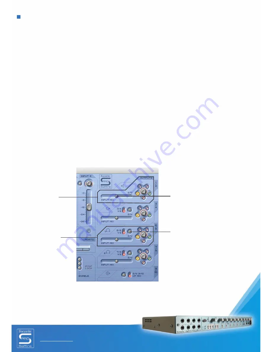
Although SaffireControl PRO’s default setting will enable all inputs to be heard, make sure that the crossfader for the relevant
output pair is sufficiently over to the left if you wish to listen to the sources being recorded. If you are still not hearing the relevant
input, the fader for that input may not be high enough in the Input Mix section (check the ‘Creating an Input Mix’ section for details).
However, if attempting to monitor a main mix playback from the sequencer (any audio routed to outputs 1 and 2), you will need to
make sure that Saffire PRO has been set up as the input/output audio device within that sequencer, then ensure that the
corresponding output (whatever your speakers or headphones are connected to) has 1/2 selected as its S/W track within the output
section of the SaffireControl PRO software (always the case for the Main Monitors.) Also the relevant crossfader must be set to
monitor the S/W playback (set middle or right) as shown in the diagram below. Read the relevant monitoring sections of this User
Guide for details.

The colour of the power LED will channge depending on wether or not the external power supply is connected. Whilst using
the PSU, the LED will be green. Whilst powering the unit via a firewire buss, the LED will be red.

On Outputs 3-8, there is the option of
routing Playback (S/W) tracks 1/2 or the
corresponding tracks (in this case 5/6)
from the sequencer to the output. (5/6
relates to Saffire PRO Outputs 5/6 within
the sequencer.)

Controls for Outputs
1 and 2

Controls for Outputs
3 and 4 and
Headphones 1 
(same signal)

Crossfader must be in a central
position for Inputs and Playback
tracks to be heard. If this is set
totally right, only Playback (S/W)
tracks 1/2 will be heard

Summary of Contents for Saffire Pro 26 I/O

Page 1: ...User Guide FA0110 01 E OE ...

Page 2: ...tput settings Monitoring options 10 Analogue output settings 10 Additional options on Outputs 3 10 11 Creating an Input Mix 12 Setting up a Headphones Mix 13 S CARD and TRACK modes 13 AC3 Thru mode 13 Linking Output controls CTRL LINK 14 DIM and Active Monitor Pad switches 14 Setting different sample rates 15 Synchronising Saffire PRO 26 i o 16 Using Inserts 17 Saving Recalling settings 17 Changin...

Page 3: ...plying playback audio directly to an amp headphones or powered speakers There are also digital audio options S PDIF and ADAT plus connectors for sending and receiving MIDI and Word clock Additionally the hardware can function in standalone mode powered by external PSU for tracking or mixing without using a computer The accompanying software application SaffireControl PRO provides further recording...

Page 4: ...ant output pair is sufficiently over to the left if you wish to listen to the sources being recorded If you are still not hearing the relevant input the fader for that input may not be high enough in the Input Mix section check the Creating an Input Mix section for details However if attempting to monitor a main mix playback from the sequencer any audio routed to outputs 1 and 2 you will need to m...

Page 5: ... In addition on the front panel there are 8 1 4 TRS balanced jack inputs for recording line level signals Inputs 1 8 These automatically override the XLR inputs on the rear panel if both sets are connected If you wish to record a guitar inputs 1 and 2 can be used to route a signal directly from the instrument DI to the sequencer Instrument select buttons are included for these inputs to allow matc...

Page 6: ...chronising to external equipment with two standard 5 pin MIDI sockets allowing MIDI data to be received and transmitted A 3 pin locking power socket allows the provided power supply to be connected should Firewire bus power not be preferred if preserving computer battery or using the hardware in standalone mode without a computer or if wishing to use the extra headroom feature Finally two Firewire...

Page 7: ...s the output 11 Mute output switch mutes the output 12 Playback S W 1 2 or 3 4 to Outputs 3 4 switch allows a main mix to be sent to outputs 3 and 4 13 Select Unit switch selects which Saffire PRO will be controlled when multiple interfaces are in use 14 Digital Input Enable switches activate the corresponding digital inputs 15 Identify Unit switch identifies the SaffireControl currently being con...

Page 8: ...ng gain pot on Saffire PRO s front panel Turn the dial clockwise to increase the input gain ensuring that the Overload LED does not light If you are experiencing any low frequency problems such as proximity effect or rumble engage the high pass filter button on the hardware which will reduce any signal below 120Hz If using either Input 1 or 2 a lower input impedance 150 may be set by pressing the ...

Page 9: ...record an ADAT signal at 44 1 kHz to 96 kHz connect an optical cable to either of the rear panel inputs 1 8 ADAT 1 or 9 16 ADAT 2 These relate to Saffire PRO Inputs 11 18 and 19 26 respectively and will show up in the sequencer as such Once connected the corresponding ADAT ENABLE switch in the SaffireControl PRO software SYNC section must be activated See the Synchronising Saffire PRO section for ...

Page 10: ...Outputs 1 2 within SaffireControl PRO the top right section However for the next section down Outputs 3 and 4 S W relates to the playback signals sent back to SaffireControl Outputs 3 and 4 from the sequencer unless set to 1 2 using the switch above See sections below for details 2 Gain control knob or dial adjusts the level of the stereo pair of outputs 3 Dim switch this reduces the digital level...

Page 11: ...than two channels and therefore wanting to send different signals to each of the Saffire PRO outputs the switch should be set to 3 4 whereby anything set to Outputs 3 and 4 within the sequencer will appear on the right side of the crossfader For an instant way of setting up Saffire PRO for multi channel mixdown or layback check out the S CARD button in the bottom half of the software window See th...

Page 12: ...ink button this links the levels of the inputs either side of the switch and auto pans them hard left and right 5 Solo and Mute switches these solo and mute Inputs 1 8 The Input mix group fader select switches choose which signal group of all the inputs is controlled by the eight Input Mix faders For example if you wish to increase the levels of the S PDIF Input click the S PDIF switch This activa...

Page 13: ...s This does away with the need to manually configure each output pair if you wish to quickly change from recording to mixing down or playing back in surround sound S CARD soundcard mode is activated by the S CARD switch This makes Saffire PRO behave like a standard 10 output soundcard where Saffire PRO Outputs 1 10 from the sequencer route directly to the Saffire PRO hardware Outputs Note that reg...

Page 14: ...Pad switches The DIM and Active Monitor Pad switches provide two means of reducing the level of the Outputs for two specific purposes The DIM switch is a way of temporarily reducing the level if the volume needs to be cut quickly e g if a phone rings The switch attenuates the digital level by 18dB when active Using this switch means that the level can be restored to an identical volume after the i...

Page 15: ...that Saffire PRO s sample rate matches that of the sequencer session as well as any attached digital audio equipment especially if attempting to synchronise to it see next section When sample rates above 44 1 and 48 kHz are set the functionality of SaffireControl PRO may change depending on what digital inputs are active For details of the software operational differences as sample rate changes co...

Page 16: ...ut to ensure the most successful conversion The clock is embedded within its digital audio data stream and will ensure that no unwanted artefacts normally clicks or dropouts occur When two or more devices are both transmitting digital audio streams to the inputs of the Saffire PRO they must be synchronised with each other by locking to an external device s clock This can come from a separate word ...

Page 17: ...Jack going to two TS Jacks For anyone wishing to make their own cables the Tip of the TRS Jack plugged into the Line Input is the send signal and the Ring is the return Saving Recalling settings The SAVE switch within SaffireControl PRO allows the software settings to be saved as a file to the computer s hard disk for instant recall at a later date Clicking the switch brings up a standard browser ...

Page 18: ...Saffire PRO s MIDI Out to the MIDI input of the device Make sure that Saffire PRO is first selected as an interface within the sequencer s MIDI preferences before attempting to send and receive data A MIDI Thru switch is also provided within SaffireControl PRO This converts the MIDI Out port into a MIDI Thru meaning that MIDI data will route straight from the MIDI In to the MIDI Out regardless of ...

Page 19: ...ly click the display box that shows the name of the active device This opens up a separate window where the device can be renamed To switch to controlling another device click the switch on the right which brings up a drop down list from which another Saffire PRO can be selected Note We do not recommend diasy chaining more than 3 Saffire PRO hardware units Click ID to identify the Saffire PRO bein...

Page 20: ... turns on phantom power for Inputs 5 8 Pressing and holding holding for 1 second activates ADAT SMUX Input 9 16 and routes the signal to analogue outputs 1 8 when using ADAT or 5 8 when using SMUX The power LED on the front panel will turn off indicating successful setup This will automatically synchronise Saffire PRO to that lightpipe input The optical input will turn off however if there is not ...

Page 21: ...ifferent sample rates by detailing 6 modes described below Note The Audio MIDI setup cannot be used to switch to higher sample rates This must be done using SaffireControl PRO Mode 1 44 1 48kHz Default mode I O 8 Analogue 2 S PDIF 16 ADAT Total 52 SaffireControl PRO Full control Mode 2 44 1 48kHz ADAT I O disabled I O 8 Analogue 2 S PDIF Total 20 SaffireControl PRO Full control but no ADATs The co...

Page 22: ...RO Full control but no ADATs The control panel is the same as the panel described in Mode 2 Mode 5 176 4 192kHz Default mode I O 8 Analogue 2 S PDIF Total 20 SaffireControl PRO No Input Mix capabilities The control panel is the same as the panel described in Mode 3 Mode 6 AC3 pass thru I O 8 Analogue 2 S PDIF Total 20 SaffireControl PRO No Input Mix capabilities This looks similar to the control p...

Page 23: ...h on the hardware set correctly The INST LED must be active Is the slider for the monitoring pair of outputs far enough to the left towards the INPUT MIX position If over to the right in the S W position only the tracks from the sequencer will be heard No signal heard at one of the outputs Is the level of the corresponding pair of outputs set high enough either within SaffireControl PRO or on the ...

Page 24: ... word clock on S PDIF Sync to word clock on BNC word clock input Sync to word clock on ADAT1 or ADAT2 inputs A D Dynamic Range 110dB A weighted all inputs D A Dynamic Range 110dB A weighted all outputs Clock Jitter 250 pico seconds Sample rate 44 1 to 192kHz WEIGHT and DIMS 3kg 35cm x 4 5cm x 23 5cm ANALOGUE INPUTS Mic 8 x XLR on front panel Mic Gain 13dB to 60dB Line 1 8 2 x 1 4 TRS Jack front pa...

Page 25: ...4 1 48kHz 16 channels 1 x ADAT In Out 88 2 96kHz 8 channels S MUX Word clock input on BNC Word clock output on BNC MIDI I O 1 in 1 out thru on rear panel FIREWIRE S400 2 ports POWER Either via FIREWIRE or external PSU included HEADPHONE MONITORING 2 x 1 4 TRS Jack on front panel mirrors outputs 5 6 and 7 8 High power headphone drivers E OE ...

Reviews: