


27
Handler I, II & III Operator’s Manual - October 2008
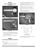
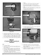
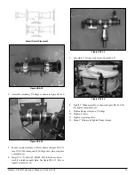
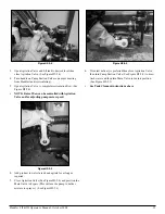
Figure H3-4.27
Install 2” Tee (10-11100) to bottom of tank (use sealant),
see figure H3-4.27
Figure H3-4.28
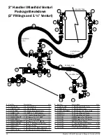
Install fittings as shown in figure H3-4.28.
If using a pump/motor combination different than shown in
figure H3-4.26 may require repositioning of the pump to di-
rect exhaust away from the tank. This may require drilling
extra holes in plate.
2.
3.
4.
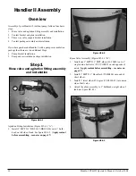
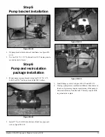
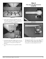
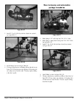
Three inch pump and recirculation
package installation
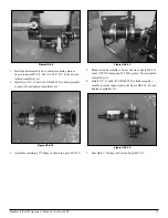
Figure H3-4.29
Mount pump to “Z” rails using four 5/16’ X 1 ½” bolts.
Mount pump to pump bracket using four 5/16’ X 3/4” bolts.
See figure H3-4.29
Install 2” Tee (10-11100) to bottom of tank (use sealant),
see figure H3-4.27
Figure H3-4.30
Install fittings as shown in figure H3-4.30.
If using a pump/motor combination different than shown in
figure H3-4.29 may require repositioning of the pump to di-
rect exhaust away from the tank. This may require drilling
extra holes in plate.
1.
2.
3.
4.
5.
Summary of Contents for Handler I
Page 2: ......
Page 48: ...48 Handler I II III Operator s Manual October 2008...