Model 920 Ethernet Data Multiplexer Manual
Focal Technologies Corporation
Page 2-1
A Moog Inc. Company
920-0603-00 Rev K
2.0
System Overview
Model 920 EDM systems are sold as pairs to provide a transparent Ethernet, EtherCAT, and CAN Bus link over
fiber optics. The installed optical transceivers determine the rated optical link speed, fiber type and link distance.
The optical link uses a proprietary data protocol ensuring 100% throughput of all linked Ethernet channels with
CAN Bus at up to 500 KBaud and full system diagnostics. The Ethernet channels are non-switched ensuring
low deterministic latency, and also ensuring that the Ethernet packets are not mixed between links, i.e. data
to/from port 1 will always be to/from port 1 on the far side of the optical link.
The uplink and downlink are combined on a single fiber
– singlemode or multimode (standard) – with a passive
optical coupler known as a wavelength division multiplexer (WDM). Basic systems usually operate with a 1310
nm uplink and 1550 nm downlink. In larger systems, multiple 920 EDM units may be combined on a single fiber
using a coarse wavelength division multiplexer (CWDM) to take advantage of the high bandwidth of optical
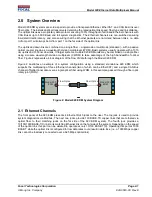
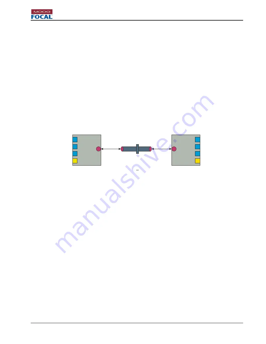
fiber. Figure 2 represents a block diagram of the flow of data through the Model 920 EDM.
Figure 2 illustrates an example of a system configuration using a standard, standalone 920 EDM, which
supports the multiplexing of three Ethernet channels (two of which can be EtherCAT) and a single CAN Bus
channel of bidirectional data over a single optical fiber using WDM, in this example, passed through a fiber optic
rotary joint (FORJ).
FORJ
Model 920
EDM
Model 920
EDM
Fiber Optics
Fiber Optics
Figure 2: Model 920 EDM System Diagram
2.1 Ethernet Channels
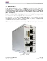
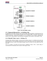
The front panel of the 920 EDM presents 4 Ethernet RJ45 jacks to the user. The top jack is used to provide
system diagnostics via Modbus. The next two jacks provide 100 BASE-TX copper links that are tethered via
optical fiber to their matching jacks on the far side of the 920 EDM system. The fourth jack provides a
10/100/1000 BASE-T(X) link to its matching Ethernet link on the far side of the system. Depending on the speed
of the optical link, this port can be derated to operate at only 10/100 BASE-T(X). Operating this port at 1000
BASE-T while the optical link is configured for low data rates could result in data loss. (i.e. a 1000 Mbps copper
link cannot be losslessly connected over a 625 Mbps optical link)


