


Model 920 Ethernet Data Multiplexer Manual
Focal Technologies Corporation
Page iii
A Moog Inc. Company
920-0603-00 Rev K
LIST
OF
TABLES
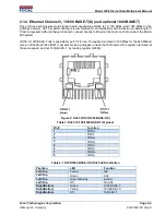
Table 1: RJ45 10/100 BASE-T(X) pinout ......................................................................................................... 2-3
Table 2: 10/100 BASE-T(X) RJ45 LED Indication ........................................................................................... 2-3
Table 3: RJ45 10/100/1000 BASE-T(X) pinout ................................................................................................ 2-4
Table 4: 10/100/1000 BASE-T(X) RJ45 LED Indication .................................................................................. 2-4
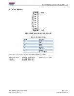
Table 5: 8-Pin Header Pinout ........................................................................................................................... 2-6
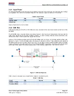
Table 6: Input Power ........................................................................................................................................ 2-7
Table 7: CAN Bus ............................................................................................................................................ 2-7
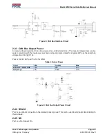
Table 8: Output Power ..................................................................................................................................... 2-8
Table 9: 10/100/1000 BASE-T(X) RJ45 LED Indication .................................................................................. 2-9
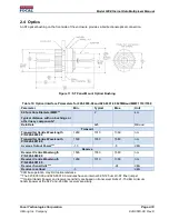
Table 10: Optical Interface Parameters for 920-8000-00 and 920-8001-00 625MBaud MMF 1310/1550 .... 2-10
Table 11: Optical Interface Parameters for 920-8000-01 and 920-8001-01 2.5GBaud MMF 1310/1550 ..... 2-11
Table 12: Optical Interface Parameters for 920-8000-02 and 920-8001-02 2.5GBaud SMF 1310/1550 ...... 2-11
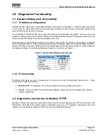
Table 13: Factory Default Network Parameters ............................................................................................... 3-1
Table 14: Electrical Specification ..................................................................................................................... 6-3
Table 15: Environmental Specification ............................................................................................................. 6-3
LIST
OF
FIGURES
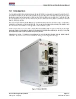
Figure 1: Model 920 EDM ................................................................................................................................ 1-1
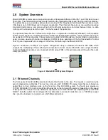
Figure 2: Model 920 EDM System Diagram .................................................................................................... 2-1
Figure 3: Model 920 EDM Front Side .............................................................................................................. 2-2
Figure 4: RJ45 10/100 BASE-T(X) ................................................................................................................... 2-3
Figure 5: RJ45 10/100/1000 BASE-T(X) .......................................................................................................... 2-4
Figure 6: 8-Pin Header, Molex P/N 502352-0800 ............................................................................................ 2-6
Figure 7: CAN Bus Repeater ........................................................................................................................... 2-7
Figure 8: CAN Bus Interface Circuit ................................................................................................................. 2-8
Figure 9: CAN Bus Output Power Circuit ......................................................................................................... 2-8
Figure 10: Model 920 EDM LEDs .................................................................................................................... 2-9
Figure 11: ST Panel Mount Optical Bushing .................................................................................................. 2-10
Figure 12: Modbus TCP Protocol Stack ........................................................................................................... 3-2
Figure 13: Sample .NET GUI for Modbus TCP Access to Model 920 ............................................................. 3-3
Figure 14: Telnet Interface ............................................................................................................................... 4-1
Figure 15: Model 920 EDM Rear with DIN Rail Mount Adaptors ..................................................................... 6-1


