background image

www.fmiproducts.com

112127-01E

30

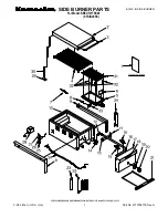
PARTS

MODELS SBVBND AND SBVBPD

4

4

17

18

19

21

23-1

23-4

23-2

23-3

6

4

22

10

16

11

11

8

1

25

25

4

13

14

20

20

4

5

3

26

2

24

21

7

12

15

4

9

Summary of Contents for SBVBND

Page 1: ...hbor s phone Follow the gas supplier s instructions If you cannot reach your gas supplier call the fire department Installation and service must be performed by a quali fied installer service agency or the gas supplier INSTALLER Leave this manual with the appliance CONSUMER Retain this manual for future reference CAST IRON STOVE AND B VENT FREESTANDING FIREPLACE HEATER BURNER SYSTEM OWNER S OPERAT...

Page 2: ...ompletely before trying to assemble oper ate or service this stove with burner system Improper use of this stove with burner system can cause serious injury or death from burns fire explo sion electricalshockandcarbon monoxide poisoning DANGER Carbonmonoxide poisoning may lead to death This stove complies with the National Safety Standards and is listed and tested by PFS Corporation to ANSI Z21 50...

Page 3: ...ner system WARNING Any change to this stove or burner system or it s controls can be dangerous Do not modify this stove with burner system under any circumstances Any parts removed for servicing must be replaced prior to operating burner system WARNING Do not use a blower insert heat exchanger insert or other accessory not approved for use with this stove WARNING This appliance is only for use wit...

Page 4: ... are in the room with stove Keeptheareaaroundyourstove clear of combustible materials gasoline and other flammable vapor or liquids Do not run burner system where these are used or stored 1 For propane LP burner system do not place propane LP supply tank s inside any structure Locate propane LP supply tank s outdoors To prevent performance problems do not use propane LP fuel tank of less than 100 ...

Page 5: ...nce to local codes use the current National Fuel Gas Code ANSI Z223 1 NFPA 54 Available from American National Standards Institute Inc 1430 Broadway New York NY 10018 National Fire Protection Association Inc Batterymarch Park Quincy MA 02269 PRODUCT IDENTIFICATION PRODUCT FEATURES OPERATION This B vent cast iron stove with burner system is clean burning and vents vertically Heat is generated by bo...

Page 6: ...l or cloth wall coverings or operating stove with burner system where impurities such as but not limited to tobacco smoke aromaticcandles clean ingfluids oilorkerosenelamps etc intheairexist maydiscolor walls or cause odors LOCATION AND SPACE REQUIREMENTS Determine the safest and most efficient loca tion for your FMI PRODUCTS LLC B vent cast iron stove Make sure that rafters and wall studs are not...

Page 7: ...ood frame enclosure Two or more people must carefully lift stove up and out of wooden crate 3 Remove plastic bag from stove body 4 Remove back panel from stove see Fig ure 6 Use an adjustable wrench or a 10 mm socket Remove 4 bolts and washers Keep bolts and washers to reattach back panel later 5 Remove bubble wrapped log set rod and screen from stove Remove all protective packaging applied for sh...

Page 8: ...ombustibles This appliance is equipped with a safety control system de signed to protect against improper venting of combustion products It is very important that the venting system maintain its balance between the combustion air intake and the flue gas exhaust Certain limitations apply to vent configurations and must be strictly followed WARNING This gas stove with burner system and vent as sembl...

Page 9: ... regarding venting through side wall Figure 8 Vertical Venting Through Ceiling Using Two 90º Elbows Oxford Model Shown This burner system must be properly con nected to a venting system This burner system is equipped with a vent safety shutoff system Use only vents labeled FOR EXTERIOR USE above the roofline Consult the authority having jurisdiction to select the correct gas vent diameter Avoid us...

Page 10: ...e the chase as you would the outside walls of your home This is especially im portant in cold climates Minimum clearance between vent pipes and combustible materials such as insulation is 1 CHECKING VENT CAPACITY Complete all gas piping electrical and vent connections After adjusting the burner system and lighting the main burners allow a couple of minutes for warm up Hold a lighted match just und...

Page 11: ... 1 2 foot length Oversized chimneys should be relined with appropriate listed relining systems Clean out access may be required RELINING SYSTEMS Suitability and approval of relining materials should be determined Condition size height and termination of the chimney to be relined must be determined No substitution of components should be made Joints and connectors should be made according to manufa...

Page 12: ...s A simple spillage test can be conducted if spillage is suspected See Checking Gas Connection page 15 CAUSES OF SPILLAGE AND CORRECTIVE ACTION Incorrect Vent Sizing If the vent is too small or too short spillage may occur If the vent is too large excessive dilution air may cool flue gases and reduce draft causing spillage The vent cap size should also be checked Check manufac turer s instructions...

Page 13: ...ructions included with conver sion kit INSTALLING GAS PIPING TO STOVE LOCATION WARNING A qualified in staller or service person must connect burner system to gas supply Follow all local codes CAUTION For propane LP units never connect burner system directly to the propane LP supply This burner system requires an external regulator notsupplied Installtheexternal regulator between the burner system ...

Page 14: ...trap drip leg in supply line as shown in Figure 15 Locate sediment trap drip leg where it is within reach for cleaning Install in piping system between fuel supply and burner system Locate sediment trap drip leg where trapped matter is not likely to freeze A sediment trap traps mois ture and contaminants This keeps them from going into burner system gas controls If sedi ment trap drip leg is not i...

Page 15: ...g propane LP supply tank valve for propane LP gas burner system or opening main gas valve located on or near gas meter for natural gas burner system or using compressed air 4 Check all joints of gas supply piping sys tem Apply noncorrosive leak test solution to all gas joints Bubbles forming show a leak Correct all leaks at once Figure 17 Equipment Shutoff Valve Figure 18 Checking Gas Joints for P...

Page 16: ...s are in the positions on the unit as pictured in Figure 20 If wires are not connected as shown the switch will not work 2 Route the 25 ft wire through openings provided on the sides of the burner system to a convenient location to mount your switch Figure 20 Control Valve Terminals To Control Switch or Optional Accessory 3 Connect one bare wire end to each of the terminals of the GWMS2 wall switc...

Page 17: ... Glass Door REMOVING REPLACING GLASS DOOR Cast Iron Stove Body Cast Iron Stove Body CAUTION Do not operate this burner system with a bro ken glass door panel or without the glass door panel securely in place For replacement part information see Replacement Parts page 29 1 Use reverse directions for installing rear cover page 16 Remove stove insert from cast body 2 Remove screws from 2 tabs at top ...

Page 18: ...ent Parts page 29 1 Remove glass door See Removing Re placing Glass Door page 17 2 Place log 1 back log on top of grate Make sure notches in the bottom of log fit over the grate see Figure 24 3 Rest log 2 large front log on the pins on the front part of grate see Figure 25 4 Place log 3 crossover log onto rear and front logs Make sure it is seated properly into notch on front log and over the rais...

Page 19: ...7 Pull ember material apart into pieces no larger than a dime Place these pieces loosely and sparingly directly onto the exposed section of front burner and along space between burner and grate prongs see Figure 28 This will create the glowing ember appearance as the flame touches the ember material Do not block air slots by using too much ember material in one area It is not necessary to use all ...

Page 20: ...Valve Gas Control Knob Piezo Ignitor FOR YOUR SAFETY READ BEFORE LIGHTING WARNING If you do not fol low these instructions exactly a fire or explosion may result causing property damage per sonal injury or loss of life A This appliance has a pilot which must be lighted by hand When lighting the pilot follow these instructions exactly B BEFORE LIGHTING smell all around the appliance area for gas Be...

Page 21: ...s door see Removing Replacing Glass Door page 17 OPERATION Continued OPTIONAL REMOTE OPERATION Note All remote control accessories must be purchased separately seeAccessories page 29 Follow instructions included with the remote control NOTICE Youmust lightthepilot before using the hand held re mote control unit See Lighting Instructions page 20 After lighting let pilot flame burn for about one min...

Page 22: ...Call a qualified service person to readjust the pilot if necessary The height of the thermopile must be 3 8 to 1 2 above the pilot flame as shown in Figure 33 The flame from the pilot burner must ex tend beyond the thermopile If your pilot assembly does not meet these requirements turn burner system off see To Turn Off Gas to Appliance page 21 see Troubleshooting page 24 CLEANING AND MAINTENANCE W...

Page 23: ...placing Glass Door page 17 for instructions for replacing glass door WARNING Do not operate burnersystemwiththeglassdoor removed cracked or broken CLEANING AND MAINTENANCE Continued PILOT AND BURNERS Remove ember material before cleaning burners and replace when cleaning is complete Burner and controls should be cleaned with compressed air to remove dust dirt or lint Use a vacuum cleaner or small ...

Page 24: ...bing Keep ignitor cable dry 3 Tighten nut holding piezo ignitor Nut is located behind the mounting bracket 4 Replace ignitor cable 5 Replace piezo ignitor 6 Replace pilot assembly 7 Replace pilot assembly When ignitor button is pressed there is spark at pilot but no ignition 1 Gas supply turned off or equipment shutoff valve closed 2 Control knob not in PILOT position 3 Control knob not pressed in...

Page 25: ...o low 3 Thermopile leads discon nected or improperly con nected 4 Thermopile is defective 1 Clean burner see Cleaning and Maintenance page 22 or replace burner orifice 2 Contact local propane LP or natural gas company 3 Reconnect leads see Wiring Diagram page 28 4 Replace thermopile Delayed ignition burner 1 Manifold pressure is too low 2 Burner porting or orifice clogged 1 Contact local propane L...

Page 26: ...T packed with any type of material 3 Follow venting configuration instructions on pages 7 thru 12 Burner system produces a clicking ticking noise just after burners are lit or shut off 1 Metalexpandingwhileheating or contracting while cooling 1 This is normal If noise is excessive contact qualified service person Remote does not function 1 Battery is not installed or battery power is low 1 Replace...

Page 27: ...Gas leak See Warning statement page 26 1 Locate and correct all leaks see Checking Gas Connec tions page 15 Dark residue on logs or inside of burner system 1 Improper log placement 2 Air holes at burner inlet blocked 3 B u r n e r f l a m e h o l e s blocked 4 Improper vent configura tion 1 Properly locate logs see Installing Logs Lava Rock and Glowing Embers page 18 2 Clean out air holes at burne...

Page 28: ...3 5 W C Minimum Inlet Supply Pressure 5 W C Dimensions HxWxD 27 x 21 1 2 x 18 68 6 x 54 6 x 45 7 cm SBVBPD Rating 28 000 Btu Hr Gas Type Propane LP Gas Manifold Pressure 10 W C Minimum Inlet Supply Pressure 11 W C Dimensions HxWxD 27 x 21 1 2 x 18 68 6 x 54 6 x 45 7 cm WIRING DIAGRAM CAUTION Label all wires prior to disconnection when servicingcontrols Wiringerrors can cause improper and dan gerou...

Page 29: ... HELD REMOTE CONTROL KIT MRC For all Remote Ready Models Allows the gas log heater to be turned on and off by using a hand held remote control Purchase these accessories from your local dealer If they can not supply these accessories call FMI PRODUCTS LLC at 1 866 328 4537 for information You can also write to the address listed on the back page of this manual WALL MOUNTED ON OFF SWITCH GWMS2 For ...

Page 30: ...www fmiproducts com 112127 01E 30 PARTS MODELS SBVBND AND SBVBPD 4 4 17 18 19 21 23 1 23 4 23 2 23 3 6 4 22 10 16 11 11 8 1 25 25 4 13 14 20 20 4 5 3 26 2 24 21 7 12 15 4 9 ...

Page 31: ...tch Screw 4 12 105468 02 Valve Bracket 1 13 14512 Valve Natural 1 14513 Valve Propane LP 1 14 14571 Pilot Assembly Natural 1 14583 Pilot Assembly Propane LP 1 15 097159 04 Ignitor Piezo 1 16 107195 01 Bracket Spill Switch 1 17 14597 Burner Natural 1 14598 Burner Propane LP 1 18 104506 16 Orifice Natural 1 104506 17 Orifice Propane LP 1 19 14528 Brass Elbow 1 20 112050 01 Brass Fitting 2 21 101628 ...

Page 32: ...l provide original factory replacement parts Failure to use original factory replacement parts voids this warranty Travel handling transportation diagnostic material labor and incidental costs associated with warranty repairs unless expressly covered by this warranty are not reimbursable under this warranty and are the responsibility of the owner All warranty will be voided if this product is used...

Reviews: