


Doc. No.: OMS500000104
Rev: A Page 6 of 42
Subject to contractual terms and conditions to the contrary, this document and all the information contained herein are the confidential and exclusive
property of FMC Technologies, and may not be reproduced, disclosed, or made public in any manner prior to express written authorization by FMC.
2.0
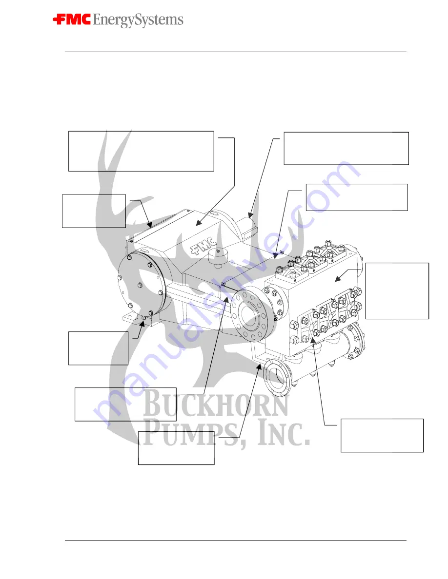
M28 Pump Features
Exceptional design, workmanship, materials, and over 100 years experience building pumps are
features you’ll find built into every FMC pump.
Oil level sight gage
allows remote
monitoring of oil
level and condition.
Choice of straight-keyed shaft or optional
mounting flange and spline for direct
coupling of hydraulic motor drives.
Magnetic drain
plugs remove
tramp iron from
the oil bath.
State of the art plungers and
packing provides unmatched
service life in even the toughest
applications.
Integrally cast and
machined feet to provide
rigid and precise
mounting.
Individual clamped cylinder
covers allow removal of
plungers through the front
of the fluid cylinder.
Abrasion resistant
or disc type valves
feature tough,
durable materials
and generous flow
areas to extend
service life.
Plunger rods and packing can be
removed and replaced without
disassembling the power end.
Heavy-duty power ends are machined from a one-
piece gray iron casting for long service life. All
pumps incorporate a reliable splash lube system
with gravity feed return to sump. Pressure
lubrication of internal bearings is an option.