FMB MB9AA30N SERIES User Manual Download Page 14

Bluemoon-EVB

 Hardware V1.1.0 

Chapter 4 Program Download 

MCU-UM-510106-E-10 

– Page 14 


4.2  JTAG Debug 

The demo board supports standard 20-pin JTAG debugging and programming .The user is 
recommend using IAR system tools including the emulator and complier. The steps as: 

1.  Connect the board as 

chapter


3.2.4 (Connection on JTAG)

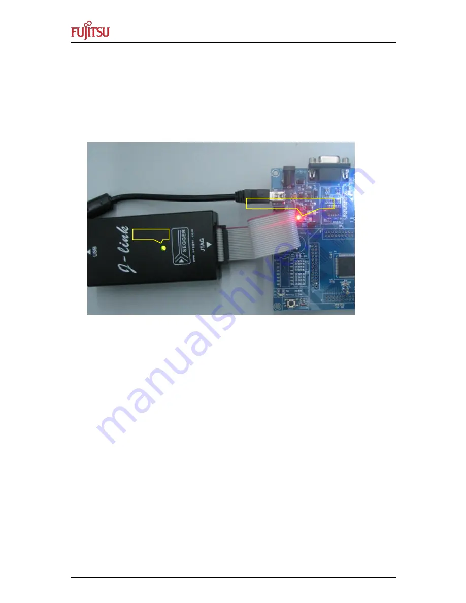
2.  As  the  Figure  4-3  shows,  the  J-Link  led  will  turn  green,  EVB  D4  (power  supply 

indication) will light. 


Figure 4-4: JTAG and EVB Connect


3.  Open the project file, as Figure 4-5 shows 

JTAG LED 

Power supply LED indication 

Summary of Contents for MB9AA30N SERIES

Page 1: ...nductor Design Chengdu Co Ltd User Manual MCU UM 510106 E 11 32 BIT MICROCONTROLLER MB9AA30N SERIES BLUEMOON EVB HARDWARE USER MANUAL ARM and Cortex M3 are the trademarks of ARM Limited in the EU and other countries ...

Page 2: ...ng such information FUJITSU SEMICONDUCTOR assumes no liability for any infringement of the intellectual property rights or other rights of third parties which would result from the use of information contained herein The products described in this document are designed developed and manufactured as contemplated for general use including without limitation ordinary industrial use general office use...

Page 3: ...8 3 2 2 EVB runs normal Connection 9 3 2 3 Connection on serial programmer 10 3 2 4 Connection on JTAG 11 4 PROGRAM DOWNLOAD 12 4 1 Serial programming 12 4 2 JTAG Debug 14 5 EACH MODULE DESCRIPTION 17 5 1 Main Interfaces Overview 17 5 2 Power Supply 21 5 3 LCD Display and control 22 5 4 Temperature Sample 23 5 5 RTC calibration 24 6 EACH FUNCTION OPERATION 25 6 1 Operation Overview 25 6 2 EV Board...

Page 4: ...Bluemoon EVB Hardware V1 1 0 Contents MCU UM 510106 E 10 Page 4 7 TROUBLE SHOOT 30 8 ADDITIONAL INFORMATION 31 9 APPENDIX 32 9 1 List of Figures and Tables 32 ...

Page 5: ...stem block each function definition list operation steps and trouble shoot 1 2 Definitions Acronyms and Abbreviations 1 3 Document Overview The rest of document is organized as the following Chapter 2 explains Overview and Features Chapter 3 explains System Block and Connection Chapter 4 explains Program Download Chapter 5 describes Each Module Description Chapter 6 describes Each Function Operati...

Page 6: ...ated 8COM segment LCD driver circuit and RTC circuit etc user is capable of operating them easily Furthermore TSC keys also are provide The TSC_LIB a gave the driver and signal processing functions Otherwise user can use the EVB to evaluate MCU power consumption Figure 3 1 provides a photograph of the Bluemoon EV Board A block diagram that shows the main components of the system is provided All th...

Page 7: ... s backlight circuit a TSC key two mechanical keys a joystick key two LEDs a serial port and JTAG interface The power supply is selectable between DC 9V USB and battery Figure 3 1 shows the system block diagram Figure 3 1 System Block Diagram DC Power TSC Key Joystick Reset Key JTAG Work Led Power Led LCD Key DB9 USB Power FSDC FM3 A30 1 0024 01 PCB Bluemoon EVB V1 0 0 J3 P1 J2 J1 D2 J6 J7 J8 U6 J...

Page 8: ...board Table 3 1 Definition of Connectors on Main Board Number Port Designator Description Remarks 1 P1 serial port N A 2 J3 DC power supply 9V N A 3 J2 USB DC 5V power supply N A 4 J1 JTAG interface N A 5 J4 Jumper MCU Power selector N A 6 J5 Jumper serial programming selector MCU mode pin N A 7 J6 Jumper serial programming selector UART Txd N A 8 J7 Jumper serial programming selector UART Rxd N A...

Page 9: ...nection on normal operation Table 3 2 Definition of Connectors on Normal Operation Number Port Designator Description Remarks 2 J3 DC power supply 9V optional 3 J2 USB DC 5V power supply optional 5 J4 Jumper MCU Power selector N A 7 J6 Jumper serial programming selector Txd strobe 2 3 pin N A 8 J7 Jumper serial programming selector Rxd strobe 2 3 pin N A 10 BT2 Battery power supply optional Note D...

Page 10: ...rammer Table 3 3 Definition of Connectors on serial programmer Number Port Designator Description Remarks 1 P1 Serial port N A 2 J3 DC power supply 9V optional 3 J2 USB DC 5V power supply optional 5 J4 Jumper MCU Power selector N A 6 J5 Jumper serial programming selector MCU mode pin N A 7 J6 Jumper serial programming selector Txd strobe 2 3 pin N A 8 J7 Jumper serial programming selector Rxd stro...

Page 11: ...of Connectors on JTAG Number Port Designator Description Remarks 2 J3 DC power supply 9V optional 3 J2 USB DC 5V power supply optional 4 J1 JTAG interface N A 5 J4 Jumper MCU Power selector N A 7 J6 Jumper serial programming selector Txd strobe 2 3 pin N A 8 J7 Jumper serial programming selector Rxd strobe 2 3 pin N A 10 BT2 Battery power supply optional Note First power on then connect J Link to ...

Page 12: ...are used FUJITSU SEMICONDUCTOR MCU Programmer 1 Connect the board as chapter 3 2 3 Connection on serial programmer 2 Open the software PCWFM3 V01L04 flash exe 3 As Figure 4 1 shows select the target MCU MB9AF32L M N the crystal frequency 4M click the Open to select download file then click the Full Operation D E B P Figure 4 1 MCU Programmer 4 As Figure 4 2 shows press the SW1 MCU reset key and cl...

Page 13: ...dware V1 1 0 Chapter 4 Program Download MCU UM 510106 E 10 Page 13 5 Wait for some time As Figure 4 3 shows the download file completely Then do not strobe J5 the EVB will run normal Figure 4 3 MCU Programmer Download ...

Page 14: ...ming The user is recommend using IAR system tools including the emulator and complier The steps as 1 Connect the board as chapter 3 2 4 Connection on JTAG 2 As the Figure 4 3 shows the J Link led will turn green EVB D4 power supply indication will light Figure 4 4 JTAG and EVB Connect 3 Open the project file as Figure 4 5 shows JTAG LED Power supply LED indication ...

Page 15: ...0 Chapter 4 Program Download MCU UM 510106 E 10 Page 15 Figure 4 5 View of Project 4 Clicking right button on the project name and select Rebuild All The project will be rebuilt as Figure 4 6 shows Figure 4 6 Rebuild the Project ...

Page 16: ...1 1 0 Chapter 4 Program Download MCU UM 510106 E 10 Page 16 5 If build no error Select Project Download and Debug Figure 4 7 Download and Debug 6 As Figure 4 8 shows the download file completely Figure 4 8 Download completely ...

Page 17: ...M 510106 E 10 Page 17 5 Each Module Description Introduce Each Module 5 1 Main Interfaces Overview The EV board main interfaces example as connector display and keys As Figure 5 1 shows Figure 5 1 Connectors on Board 11 1 2 3 4 12 5 13 14 6 7 8 15 16 Bottom view 10 9 17 ...

Page 18: ...U mode pin Do not strobe J5 in any mode except serial programming mode N A 7 J6 Jumper serial programming selector Txd strobe 2 3 pin N A 8 J7 Jumper serial programming selector Rxd strobe 2 3 pin N A 9 J8 RTC calibration port N A 10 BT2 Battery power supply N A 11 U6 LCD N A 12 D4 Power supply LED indication N A 13 D2 MCU work LED indication N A 14 SW1 Mechanical key used MCU reset N A 15 SW2 Mec...

Page 19: ...10 GND N A 11 Pull down to GND N A 12 GND N A 13 TDO N A 14 GND N A 15 nRST N A 16 GND N A 17 NC N A 18 GND N A 19 NC N A 20 GND N A Table 5 4 collects the definition of J6 Table 5 4 Definition of J6 Pin Description Remarks 1 SOT0_0_EXT Connect to J8 2 SOT0_0 MCU serial 3 SOT0_0_232 RS232 Connect to U4 Table 5 5 collects the definition of J7 Table 5 5 Definition of J7 Pin Description Remarks 1 SIN...

Page 20: ...escription MCU UM 510106 E 10 Page 20 Table 5 6 collects the definition of J8 Table 5 6 Definition of J8 Pin Description Remarks 1 RTCCO_1 N A 2 NC N A 3 SOT0_0_EXT N A 4 SIN0_0_EXT N A 5 MD0 MCU mode pin 6 nRST N A 7 GND N A 8 VCC N A 9 NC N A 10 NC N A ...

Page 21: ...supply Use 9V DC power adapter which is positive inside and negative outside the EV board works in 5V condition USB power supply Use the USB power supply the EV board works in 5V condition Battery power supply Use battery power supply the EV board works in 3 3V condition Allows the three method work together the priority is DC 9V power supply USB power supply Battery power supply Connect Battery B...

Page 22: ... 22 5 3 LCD Display and control Figure 5 3 shows the LCD backlight and LCD drive circuit Figure 5 3 LCD Circuit LCD driver used internal divider resistor When 5V power used 10K internal resistor When 3 3V power used 100K internal resistor So the backlight and LCD display will become dark ...

Page 23: ...igure 5 4 shows the temperature sample circuit Figure 5 4 temperature sample ADC sample thermistor voltage to enhance RTC precision When EV board is works the AVCC always exist voltage So in low consumption power mode it will have some additional current consumption The solution is R44 voltage can t supply from MCUVCC ...

Page 24: ...h Module Description MCU UM 510106 E 10 Page 24 5 5 RTC calibration As Figure 5 5 shows RTC calibration circuit Figure 5 5 RTC calibration RTC calibration need used FUJITSU RTC Calibration tools It used calibrate RTC crystal frequency deviation ...

Page 25: ...eration Overview The EV Board power on D4 will light always anytime press SW1 the EV Board will reset The system includes three modes Normal mode system runs normal Test mode convenient for measure the MCU power consumption closed ADC LVD LCD and so on function Low power consumption mode used measure the MCU power consumption in standby RTC mode ...

Page 26: ...w power consumption mode only from normal mode 6 2 1 Start up Display The system power on D4 will away light D2 light last 2s LCD display FUJITSU last 3s As Figure 6 1 shows Figure 6 1 Start up Display 6 2 2 RTC Default Setting The system start up from power shut the RTC is set 2012 10 01 09 00 00 Figure 6 2 Display Time Note system reset the RTC will save the current value D4 D2 ...

Page 27: ... system will enter RTC setting function The LCD blink place means current setting options first is year setting option Press SW2 jumps to next option includes year month day hour minute second Press the SW3 include up down left right keys to set the value Up and left key will reduce current value down and right key will add current value Press K1 exit RTC setting function without save any setting ...

Page 28: ...ows Figure 6 4 Test Mode Display 1 In normal mode press SW2 K1 SW3 to enter test mode 2 Press SW3 the D2 will light last 0 5 s 3 In test mode press SW2 K1 SW3 to exit normal mode 4 In test mode press SW2 K1 will enter low power consumption mode Press SW2 wake up it and then enter test mode again 5 Note If don t exit test mode user should be sure not enter low power consumption mode ...

Page 29: ...Power Consumption Mode Operation In low power consumption mode standby RTC mode MCU stop but D4 is light always As Figure 6 5 shows Figure 6 5 Low Power Consumption Mode Display 1 In normal mode press SW2 K1 to enter low power consumption mode 2 Press SW2 will wake up MCU and then enter normal mode ...

Page 30: ... and pin3 3 K1 is useless When system reset or wake up the MCU from low power consumption mode don t touch the K1 If battery power supply adjustment TSC key sensitivity Refer to MCU UM 510107 E 10 Bluemoon EVB_FW docx 4 Don t exit the test mode Be sure the system don t enter low power consumption mode in test mode 5 The current in low power consumption mode See as chapter 5 4 Temperature Sample Do...

Page 31: ...Page 31 8 Additional Information For more Information on FUJITSU semiconductor products visit the following websites English version address http www fujitsu com cn fsp services mcu 32bit fm3 an html Chinese version address http www fujitsu com cn fss services mcu 32bit fm3 an html ...

Page 32: ...k Diagram 7 Figure 3 2 Connectors on Main Board 8 Figure 3 3 Connection on Normal Operation 9 Figure 3 4 Connection on Serial Programmer 10 Figure 3 5 Connection on JTAG 11 Figure 4 1 MCU Programmer 12 Figure 4 2 Connect System 12 Figure 4 3 MCU Programmer Download 13 Figure 4 4 JTAG and EVB Connect 14 Figure 4 5 View of Project 15 Figure 4 6 Rebuild the Project 15 Figure 4 7 Download and Debug 16...

Reviews: