background image


6/116 

Original Betriebsanleitung Dickstoffpumpe F 550 und Hygienepump F 560 


DD

EU
TSCH


2.2 Symbol- 

und 

Hinweiserklärung 

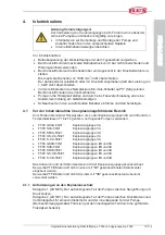
Sicherheitshinweise sind mit 

x

 einem 

Sicherheitskennzeichen 

und 

x

 einem 

Gefahrenhinweis 

gekennzeichnet. Sie helfen Ihnen, mögliche Gefahren zu erkennen, Risiken zu vermei-
den und das Gerät sicher zu betreiben. 

In der Betriebsanleitung erhalten Sie zusätzlich Handlungsanweisungen zur Gefahren-
vermeidung. 

Gefahrenhinweise sind in drei Kategorien abhängig von der Schwere einer möglichen 
Verletzung eingeteilt. Entsprechend der Schwere werden verschiedene Signalwörter 
verwendet. 

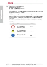
Die Bedeutung der Sicherheitskennzeichen wird durch Form und Farben (DIN 4844) 
signalisiert: 


Form 

Farbe 

Bedeutung 


Sicherheitsfarbe rot 
Kontrastfarbe weiß 

Verbot 


Sicherheitsfarbe gelb 
Kontrastfarbe schwarz 

Warnung 


Sicherheitsfarbe blau 
Kontrastfarbe weiß 

Gebot 


Summary of Contents for F 550 GS Series

Page 1: ...ating instructions Notice d instructions générale originale DEUTSCH Dickstoffpumpe Hygienepumpe F 550 F 560 Seite 2 38 High viscosity liquid pump Sanitary pump F 550 F 560 Page 39 73 Pompe à vis hélicoïdale excentrée Pompe Sanitaire F 550 F 560 Page 74 110 ...

Page 2: ...12 3 2 Ausführung mit Lagerflansch F 550 S und F 560 S 12 4 Inbetriebnahme 13 4 1 Vor der Inbetriebnahme im explosionsgefährdeten Bereich 13 4 1 1 Anforderungen an den Explosionsschutz 13 4 2 Herstellung eines Potentialausgleichs 14 4 3 Inbetriebnahme der Ausführung mit Planetengetriebe F 550 GS und F 560 GS 15 4 4 Inbetriebnahme der Ausführung mit Lagerflansch F 550 S und F 560 S 15 5 Reinigung 1...

Page 3: ...on Reparaturen ausschließlich von autorisiertem Fachpersonal x ausschließlicher Verwendung von Originalersatzteilen Die in dieser Betriebsanleitung und in den entsprechenden Anhängen hervorgehobe nen Sicherheitshinweise sind in jedem Fall zu beachten Für Schäden und Betriebsstö rungen die aus dem Nichtbeachten der Betriebsanleitung entstehen übernehmen wir keine Haftung Die Herstellergarantie erli...

Page 4: ...tische und chemische Produkte sowie Mineralölprodukte Je nach Fördergut und erforderlicher Leistung kommen dabei unterschiedliche Werk stoffe und Antriebsmotoren zum Einsatz Jede Dickstoffpumpe kann mit verschiedenen Motoren betrieben werden Als Pumpenantrieb stehen elektrische Kollektor oder Drehstrommotoren und Druck luftmotoren zur Verfügung In explosionsgefährdeter Umgebung kommen Pumpen und M...

Page 5: ...chäden an Pumpe und Motor und zu Verletzungen des Bedienpersonals führen Pumpen und Zubehör für das Fördern von Lebensmitteln sind geeignet für den Mehr wegkontakt mit allen Lebensmittelkategorien sofern eine Kontaktzeit von 24 h und eine Kontakttemperatur von 40 C einschließlich einer kurzzeitigen Erhitzung auf max 85 C nicht überschritten werden Die Dickstoffpumpen und das Zubehör sind nicht daf...

Page 6: ...n In der Betriebsanleitung erhalten Sie zusätzlich Handlungsanweisungen zur Gefahren vermeidung Gefahrenhinweise sind in drei Kategorien abhängig von der Schwere einer möglichen Verletzung eingeteilt Entsprechend der Schwere werden verschiedene Signalwörter verwendet Die Bedeutung der Sicherheitskennzeichen wird durch Form und Farben DIN 4844 signalisiert Form Farbe Bedeutung Sicherheitsfarbe rot ...

Page 7: ...enden Vorsichtsmaßnahmen nicht getroffen werden Warnung Tod schwere Körperverletzung oder erheblicher Sachschaden kön nen eintreten wenn die entsprechenden Vorsichtsmaßnahmen nicht getroffen werden Vorsicht Leichte Körperverletzung kann eintreten wenn die entsprechenden Vorsichtsmaßnahmen nicht getroffen werden Achtung Sachschaden kann eintreten wenn die entsprechenden Vorsichts maßnahmen nicht ge...

Page 8: ...zstecker Pumpe und Schlauch regelmäßig auf Betriebssicherheit Gefahr durch Verspritzen der Flüssigkeit x Maximalen Betriebsdruck und die Betriebstemperatur beachten x Bei hohem Betriebsdruck können Behälter und Schläuche plat zen oder sich lösen Sorgen Sie dafür dass es beim Einfüllen in einen Behälter nicht zu einem Überdruck kommt x Entweichende Luft und Verdrängung beim Eintauchen der Pumpe in ...

Page 9: ...tshinweis im Klemmkasten x Den Drehstrommotor zum Transport nicht an der Lüfterhaube halten x Trockenlauf vermeiden Wir empfehlen den Einbau von Trockenlaufschutzeinrichtungen wie z B Strömungswächter Kontaktmanometer Differenzdruck schalter Niveausteuerungen oder ähnliche geeignete Schutzein richtungen x Vermeiden Sie den Betrieb bei geschlossener Saugseite x Pumpe nicht der Witterung aussetzen x...

Page 10: ...hergestellt werden x Die Dickstoffpumpe so anordnen dass keine Reib und Schlagfun ken entstehen und die Betriebsbedingungen einen gefahrlosen Be trieb gewährleisten x Reparaturen an explosionsgeschützten Motoren dürfen nur vom Hersteller oder einer hierfür autorisierten Werkstatt vorgenommen werden x Beim Fördern nicht leitfähiger Flüssigkeiten besteht die Möglichkeit dass die geförderte Flüssigke...

Page 11: ...u tun haben können konstruktiv oder durch weitere Schutzmaßnahmen nicht vermindert werden Auf sie wird ggf an entsprechender Stelle hingewiesen Information Beachten Sie bei der Auswahl von Motor Pumpe Zapfpistolen und Schläuchen immer die Beständigkeitsliste 3 Pumpenbeschreibung Abb 1 Schnitt durch F 550 und F 560 1 Zentrierteil 2 Überwurfmutter 3 Außenrohr 4 Statormantel 5 Offene Gleitringdichtun...

Page 12: ...etriebe Übersetzung 1 15 9 3 2 Ausführung mit Lagerflansch F 550 S und F 560 S Pumpe F 550 Dickstoffpumpe mit Drehstrommotor für niederviskose bis hochviskose pastenartige noch fließfähige Substanzen bis 25 000 mPas nach dem Exzenterschne ckenprinzip mit Lagerflansch aus Aluminium F 550 S oder in Edelstahl F 550 SF Die Pumpen sind auch mit Stopfbuchse erhältlich F 550 SB oder F 550 SFB Pumpe F 560...

Page 13: ...d dort befestigen 4 1 Vor der Inbetriebnahme im explosionsgefährdeten Bereich Zum Fördern brennbarer Flüssigkeiten die zu den Explosionsgruppen IIA und IIB und den Temperaturklassen T1 bis T4 gehören nur folgende Pumpen verwenden x F 550 GSXA 50 21 Explosionsgruppe IIA x F 550 SXA 50 21 Explosionsgruppe IIA x F 550 SFXA 50 21 Explosionsgruppe IIA x F 560 GS XA 50 21 Explosionsgruppe IIA x F 560 S ...

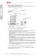
Page 14: ...lter sind separat zu erden 3 falls dies nicht schon durch die Art der Auf stellung gegeben ist Nur Schlauchleitungen 4 mit leitfähigen Schlauchverschraubungen verwenden siehe TRbF 50 Anhang B R 106 Ω Die Erdung eines metallenen Mundstückes am Schlauchende ist dann nicht erforderlich Netzanschluss 5 über eine explosionsgeschützte Steckvorrichtung einen explosi onsgeschützten Klemmkasten oder außerh...

Page 15: ...ecken bzw Druckluftschlauch anschließen Motor einschalten 4 4 Inbetriebnahme der Ausführung mit Lagerflansch F 550 S und F 560 S Antrieb durch x Drehstrommotoren 0 75 bis 1 1 kW 700 oder 930 min 1 x Druckluftmotoren FPM 4 Ex FPM 6 Ex FPM 8 Ex maximal zulässige Drehzahl 1000 min 1 Achtung x Mit Installationsarbeiten an Drehstrommotoren dürfen nur Fachkräfte beauftragt werden x Drehstrommotoren nur ...

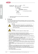
Page 16: ...ren Flüssigkeiten Anforderungen für den Explosions schutz beachten Bei klebenden und aushärtenden Flüssigkeiten Pumpe durchspülen anschließend demontieren und Gleitringdichtung sorgfältig reinigen Bei F 550 mit Elastomerstator NBR CSM FKM nach dem Reinigen einige Tropfen Gleitmittel Öl Glyzerin usw in den Stator und auf die Exzenterschnecke geben Motor kurz anlaufen lassen Bei F 560 mit Elastomers...

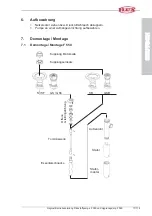
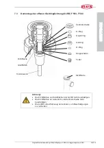
Page 17: ...wahrung Netzstecker ziehen bzw Druckluftschlauch abkuppeln Pumpe an einer Aufhängevorrichtung aufbewahren 7 Demontage Montage 7 1 Demontage Montage F 550 Kupplung Motorseite Kupplungseinsatz S SF GS GS6 SB GSB Offene Gleitringdichtung Torsionswelle Exzenterschnecke Außenrohr Stator Stator mantel ...

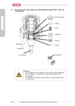
Page 18: ...D EUTSCH 7 2 Demontage Montage F 560 und F 560 FOOD S GS Außenrohr Stator Stator mantel Offene Gleitringdichtung Geschlossene Gleitringdichtung Hakenschlüssel Ø 80 90 Kupplungseinsatz Kupplung Motorseite Hakenschlüssel Ø 80 90 Torsionswelle Exzenterschnecke Innenliegendes Gewinde ...

Page 19: ...F 550 F 560 Achtung x Die Dichtflächen und Gleitflächen der GLRD nicht beschädigen x Die Dichtflächen an Außenrohr und Zentrierscheibe nicht beschädigen x Die GLRD ohne Werkzeug demontieren um Beschädigungen zu vermeiden Zentrierscheibe O Ring Gegenring Gleitring O Ring Stoppscheibe Feder Dichtfläche Gleitfläche Torsionswelle Dichtfläche ...

Page 20: ...GLRD F 560 und F 560 FOOD Achtung x Die Dichtflächen und Gleitflächen der GLRD nicht beschädigen x Die Dichtflächen an Außenrohr und Zentrierscheibe nicht beschädigen x Die GLRD ohne Werkzeug demontieren um Beschädigungen zu vermeiden Zentrierscheibe O Ring Feder Gegenring Gleitring O Ring Dichtfläche Gleitfläche Torsionswelle Dichtfläche ...

Page 21: ... GS 50 21 54 26 F 550 GS B 50 21 54 26 F 550 GS X A 50 21 Ex II 1 2 G IIA T4 PTB 99 ATEX 4050 X F 550 GS X B 50 21 Ex II 1 2 G IIB T4 PTB 99 ATEX 4051 X F 550 GS6 50 21 54 26 F 550 GS6 B 50 21 54 26 F 550 S 50 21 54 26 F 550 S B 50 21 54 26 F 550 S 50 21 TR F 550 S X 54 26 TR Ex II 2 G c IIB TX F 550 S B 50 21 54 26 TR F 550 S X A 50 21 Ex II 1 2 G IIA T4 PTB 99 ATEX 4050 X F 550 S X B 50 21 Ex II...

Page 22: ...e Ø 26 mm Ex Kennzeichnung EG Baumusterprüfbescheinigung F 560 GS 1 50 21 54 26 F 560 GS 2 50 21 54 26 F 560 GS 3 50 21 54 26 F 560 GS 3A 50 21 54 26 F 560 GS 1 X A 50 21 Ex II 1 2 G IIA T4 PTB 99 ATEX 4052 X F 560 GS 1 X B 50 21 Ex II 1 2 G IIB T4 PTB 99 ATEX 4053 X F 560 GS 2 X A 50 21 Ex II 1 2 G IIA T4 PTB 99 ATEX 4052 X F 560 GS 2 X B 50 21 Ex II 1 2 G IIB T4 PTB 99 ATEX 4053 X F 560 S 1 50 2...

Page 23: ...Original Betriebsanleitung Dickstoffpumpe F 550 und Hygienepump F 560 23 116 D D EUTSCH 9 EG Baumusterprüfbescheinigung ...

Page 24: ...24 116 Original Betriebsanleitung Dickstoffpumpe F 550 und Hygienepump F 560 D D EUTSCH ...

Page 25: ...Original Betriebsanleitung Dickstoffpumpe F 550 und Hygienepump F 560 25 116 D D EUTSCH ...

Page 26: ...26 116 Original Betriebsanleitung Dickstoffpumpe F 550 und Hygienepump F 560 D D EUTSCH ...

Page 27: ...Original Betriebsanleitung Dickstoffpumpe F 550 und Hygienepump F 560 27 116 D D EUTSCH ...

Page 28: ...28 116 Original Betriebsanleitung Dickstoffpumpe F 550 und Hygienepump F 560 D D EUTSCH ...

Page 29: ...Original Betriebsanleitung Dickstoffpumpe F 550 und Hygienepump F 560 29 116 D D EUTSCH ...

Page 30: ...30 116 Original Betriebsanleitung Dickstoffpumpe F 550 und Hygienepump F 560 D D EUTSCH ...

Page 31: ...Original Betriebsanleitung Dickstoffpumpe F 550 und Hygienepump F 560 31 116 D D EUTSCH ...

Page 32: ...32 116 Original Betriebsanleitung Dickstoffpumpe F 550 und Hygienepump F 560 D D EUTSCH ...

Page 33: ...Original Betriebsanleitung Dickstoffpumpe F 550 und Hygienepump F 560 33 116 D D EUTSCH ...

Page 34: ...34 116 Original Betriebsanleitung Dickstoffpumpe F 550 und Hygienepump F 560 D D EUTSCH ...

Page 35: ...Original Betriebsanleitung Dickstoffpumpe F 550 und Hygienepump F 560 35 116 D D EUTSCH ...

Page 36: ...36 116 Original Betriebsanleitung Dickstoffpumpe F 550 und Hygienepump F 560 D D EUTSCH ...

Page 37: ...Original Betriebsanleitung Dickstoffpumpe F 550 und Hygienepump F 560 37 116 D D EUTSCH ...

Page 38: ...38 116 Original Betriebsanleitung Dickstoffpumpe F 550 und Hygienepump F 560 D D EUTSCH ...

Page 39: ...ion with bearing flange F 550 S and F 560 S 47 4 Commissioning 48 4 1 Before starting operation in hazardous areas 48 4 1 1 Definition of explosion proof protection 49 4 2 Equipotential bonding 49 4 3 Commissioning of version with planetary gear F 550 GS and F 560 GS 50 4 4 Commissioning of version with bearing flange F 550 S and F 560 S 50 5 Cleaning 51 6 Storage 52 7 Dismantling Re assembly 52 7...

Page 40: ...ofessional and appropriate manner x repair has only been performed by authorised and qualified persons x only genuine spare parts have been used The safety instructions highlighted in these operating instructions and in the corre sponding attachments must always be observed We will not accept liability for any damages or failures due to non compliance with these operating instructions This manufac...

Page 41: ... cosmetical and chemical products as well as petro chemicals Depending on the product to be transferred different materials and drive motors are used High viscosity liquid pumps can be driven by a range of different motors Electrical commutator or three phase motors and compressed air motors are available as pump drives In an environment subject to explosion hazard pumps and motors are used which ...

Page 42: ...ty liquid pumps and the accessories are not intended to be used by uninstructed persons or by persons with limited physical sensory or intellectual capabil ities unless they are supervised by a person responsible for their safety or receive instructions from that person on how the device is to be used Children should be supervised to ensure that they do not play with the device 2 2 Symbols and sig...

Page 43: ...s information and instructions for safe and effective operation 2 4 Safety instructions All safety instructions including those in the attachments must be observed and followed Failure to follow the safety instructions may lead to serious injury or death or cause environmental and or property damage Adherence to the safety instructions contained in these operating instructions will help you to avo...

Page 44: ... worm drive pump is operated against a closed outlet an appropriate by pass pressure relief valve must be used to limit the maximum pressure Attention x Only use the pump for its intended purpose x Never leave the pump unattended x The pump has to be used in vertical position only except for hori zontal versions x Install the pump in a way which ensures that it cannot fall into the container x Onl...

Page 45: ...perature of the liquid must not exceed 40 C x The pump is for operation at a surrounding temperature of 0 C up to 40 C 2 5 For use in hazardous areas Attention x Observe the EC type examination certificate and the certificate of conformity respectively x The pump must not be used as a stationary unit in hazardous locations Fire hazard x For transferring liquids of explosion groups IIA and IIB and ...

Page 46: ...authorised repair shop x When pumping non conductive liquids there is a risk of the circu lated liquid becoming electrostatically charged Make sure to prevent any ignition hazards x The ex protected motor gear and coupling must be located out side the mobile container x The hose used must be sufficiently conductive see TRbF 50 annex B x Observe the Technical Guidelines for Flammable Liquids TRbF a...

Page 47: ...entric screw principle Eccentric worm drive pump with planetary gear ratio 1 15 9 3 2 Version with bearing flange F 550 S and F 560 S Pump F 550 high viscosity liquid pump with three phase motor or for low viscosity to high viscosity pasty still free flowing media up to 25 000 mPas according to the eccen tric screw principle Eccentric worm drive pump with bearing flange in aluminium F 550 S or Sta...

Page 48: ...en by compressed air must not exceed 1 5 kW x Before inserting the electrical plug into the socket ensure that the Start Stop switch is set to 0 Stop On compressed air motors close the valve in the air supply line x Immerse the pump into the liquid and secure it in a vertical position by the use of a compression gland or a container clamp x Immerse the flexible hose end into the container to be fi...

Page 49: ...ed screw on the explosion proof motor Connect the earth continuity conductor earth wire 2 to the designated screw on the pump If the connection between the motor and pump already provides a con ductive path for pumps for flammable liquids one of the equipotential bonding conductors may be dispensed with The containers should be grounded separately 3 if they are not already grounded by the mode of ...

Page 50: ...Insert the plug or connect the air supply hose Switch on the motor 4 4 Commissioning of version with bearing flange F 550 S and F 560 S Available drive motors x Three phase motors 0 75 to 1 1 kW 700 or 930 rpm x Compressed air motors FPM 4 Ex FPM 6 Ex FPM 8 Ex maximum speed 1000 rpm Attention x Installation maintenance and repairs to three phase motors should only be carried out by suitably qualif...

Page 51: ...ety instructions as to explosion proof equipment After each operation with sticky or self hardening products the pump should be flushed with a suitable cleaning agent The pump should then be dismantled and the mechanical seal carefully cleaned On models F 550 with elastomer stators NBR CSM FKM a few drops of lubri cant oil glycerine etc should be put on the stator and on the eccentric worm after c...

Page 52: ...e Unplug the pump or disconnect the compressed air hose Use a wall bracket to store the pump in a vertical position 7 Dismantling Re assembly 7 1 Dismantling Re assemlby F 550 S SF GS GS6 SB GSB Coupling motorside Coupling insert open sliding ring gasket torsion shaft eccentric worm outer tube stator stator housing ...

Page 53: ... F 560 53 116 E E NGLISH 7 2 Dismantling Re assembly F 560 and F 560 FOOD S GS Coupling motorside Coupling insert Hook wrench Ø 80 90 Hook wrench Ø 80 90 Closed sliding ring gasket Open sliding ring gasket Torsion shaft internal thread eccentric worm outer tube stator stator housing ...

Page 54: ...0 Attention x Make sure that the sealing and sliding faces on the SLRG will not be damaged x Make sure that the sealing faces on outer tube and centering disc will not be damaged x Do not use any tools in dismantling the SLRG to avoid any damage Centering disc o ring counter ring sliding ring o ring stop washer spring Sealing face Sealing face Sliding face Torsion shaft ...

Page 55: ...d F 560 FOOD Attention x Make sure that the sealing and sliding faces on the SLRG will not be damaged x Make sure that the sealing faces on outer tube and centering disc will not be damaged x Do not use any tools in dismantling the SLRG to avoid any damage Centering disc o ring spring counter ring sliding ring o ring Sealing face Sliding face Torsion shaft Sealing face ...

Page 56: ...gnation EC Type Examination Certificate No F 550 GS 50 21 54 26 F 550 GS B 50 21 54 26 F 550 GS X A 50 21 Ex II 1 2 G IIA T4 PTB 99 ATEX 4050 X F 550 GS X B 50 21 Ex II 1 2 G IIB T4 PTB 99 ATEX 4051 X F 550 GS6 50 21 54 26 F 550 GS6 B 50 21 54 26 F 550 S 50 21 54 26 F 550 S B 50 21 54 26 F 550 S 50 21 TR F 550 S X 54 26 TR Ex II 2 G c IIB TX F 550 S B 50 21 54 26 TR F 550 S X A 50 21 Ex II 1 2 G I...

Page 57: ...outer tube Ø 54 mm eccentric worm Ø 26 mm Ex plosion poof designation EC Type Examination Certificate No F 560 GS 1 50 21 54 26 F 560 GS 2 50 21 54 26 F 560 GS 3 50 21 54 26 F 560 GS 3A 50 21 54 26 F 560 GS 1 X A 50 21 Ex II 1 2 G IIA T4 PTB 99 ATEX 4052 X F 560 GS 1 X B 50 21 Ex II 1 2 G IIB T4 PTB 99 ATEX 4053 X F 560 GS 2 X A 50 21 Ex II 1 2 G IIA T4 PTB 99 ATEX 4052 X F 560 GS 2 X B 50 21 Ex I...

Page 58: ...58 116 Original Operating Instructions High Viscosity Liquid Pump F 550 and Sanitary Pump F 560 E E NGLISH 9 EC Type Examination Certificate ...

Page 59: ...Original Operating Instructions High Viscosity Liquid Pump F 550 and Sanitary Pump F 560 59 116 E E NGLISH ...

Page 60: ...60 116 Original Operating Instructions High Viscosity Liquid Pump F 550 and Sanitary Pump F 560 E E NGLISH ...

Page 61: ...Original Operating Instructions High Viscosity Liquid Pump F 550 and Sanitary Pump F 560 61 116 E E NGLISH ...

Page 62: ...62 116 Original Operating Instructions High Viscosity Liquid Pump F 550 and Sanitary Pump F 560 E E NGLISH ...

Page 63: ...Original Operating Instructions High Viscosity Liquid Pump F 550 and Sanitary Pump F 560 63 116 E E NGLISH ...

Page 64: ...64 116 Original Operating Instructions High Viscosity Liquid Pump F 550 and Sanitary Pump F 560 E E NGLISH ...

Page 65: ...Original Operating Instructions High Viscosity Liquid Pump F 550 and Sanitary Pump F 560 65 116 E E NGLISH ...

Page 66: ...66 116 Original Operating Instructions High Viscosity Liquid Pump F 550 and Sanitary Pump F 560 E E NGLISH ...

Page 67: ...Original Operating Instructions High Viscosity Liquid Pump F 550 and Sanitary Pump F 560 67 116 E E NGLISH ...

Page 68: ...68 116 Original Operating Instructions High Viscosity Liquid Pump F 550 and Sanitary Pump F 560 E E NGLISH ...

Page 69: ...Original Operating Instructions High Viscosity Liquid Pump F 550 and Sanitary Pump F 560 69 116 E E NGLISH ...

Page 70: ...70 116 Original Operating Instructions High Viscosity Liquid Pump F 550 and Sanitary Pump F 560 E E NGLISH ...

Page 71: ...Original Operating Instructions High Viscosity Liquid Pump F 550 and Sanitary Pump F 560 71 116 E E NGLISH ...

Page 72: ...72 116 Original Operating Instructions High Viscosity Liquid Pump F 550 and Sanitary Pump F 560 E E NGLISH ...

Page 73: ...Original Operating Instructions High Viscosity Liquid Pump F 550 and Sanitary Pump F 560 73 116 E E NGLISH ...

Page 74: ... Version équipée d un flasque de palier F 550 S et F 560 S 84 4 Mise en service 85 4 1 Avant toute mise en service en zone explosible 85 4 1 1 Exigences concernant la protection contre les explosions 86 4 2 Etablissement d une compensation de potentiel 86 4 3 Mise en service des versions F 550 GS et F 560 GS équipées d un réducteur planétaire 87 4 4 Mise en service des versions F 550 S et F 560 S ...

Page 75: ...escrites x les réparations seront exclusivement effectuées par un personnel qualifié et autori sé à cet effet x seules des pièces d origine seront utilisées Les consignes de sécurité mises en valeur dans cette notice d instructions et les annexes associées doivent être respectées dans tous les cas Nous déclinons toute responsabilité en cas de dommages ou de pannes résultant du non respect de ces i...

Page 76: ...les produits minéraux En fonction du débit et de la puissance nécessaire différents matériaux et moteurs d entraînement sont utilisés Chaque pompe pour produits visqueux peut être utilisée avec différents moteurs L entraînement de la pompe peut être réalisé par un moteur électrique universel ou tri phasé ou par un moteur pneumatique Pour une utilisation en zone explosible les pompes et moteurs doi...

Page 77: ...eut entraîner une détérioration de la pompe et du moteur ainsi que des lésions pour les opérateurs Les pompes et accessoires pour le transfert de denrées alimentaires conviennent au contact répété avec des denrées alimentaires de toutes catégories pourvu qu une durée de contact de 24h et une température de 40 C y compris un réchauffement à courte terme à 85 C maxi ne soient pas excédées Les pompes...

Page 78: ...urité Vous trouverez dans la notice d instructions des consignes vous permettant de prévenir les risques Les signaux de danger se divisent en trois catégories définies en fonction de la gravité des blessures encourues Différents termes de signalisation sont utilisés selon la gravi té La signification des symboles de sécurité est donnée par leur forme et leur couleur DIN 4844 Forme Couleur Signific...

Page 79: ...graves Le non respect des mesures de sécurité peut entraîner des dommages corporels mort éventuelle et matériels importants Attention Risque de blessures légères Le non respect des mesures de sécurité peut entraîner des dommages corporels et matériels Attention Le non respect des mesures de sécurité peut entraîner des dommages matériels Information remarque Les informations ou remarques ici rensei...

Page 80: ...ment le bon état du moteur et de son câble d alimentation de la pompe et du flexible Danger provoqué par les éclaboussures x Respecter la pression et la température de service maximum x En cas de haute pression les contenants et flexibles peuvent éclater ou se détacher Veillez lors du remplissage d un con teneur à ce qu aucune surpression ne se forme x En plongeant la pompe dans le liquide penser ...

Page 81: ...iphasé au capot de ventilateur pen dant le transport x Eviter un fonctionnement à sec Nous recommandons l installation d un dispositif contre un fonctionnement à sec comme par exemple Débit mètre Manomètre de contact interrupteur à pression de difference Commande de niveau ou des dispositifs de protec tion similaires x Eviter une opération si l entrée de la pompe est fermé x La pompe doit toujours...

Page 82: ... norme EN 60079 14 x Disposer la pompe pour produits visqueux de sorte que les étincelles dues aux frottements et aux chocs ne puissent se produire et que les conditions de service permettent d utiliser l appareil sans aucun risque x Les réparations sur les moteurs anti explosions ne doivent être effectuées que par le fabricant ou un atelier agréé x Lors du transport de liquides non conducteurs il...

Page 83: ...peuvent pas être évités par une modification ou par la mise en oeuvre de mesures de protection Ils sont le cas échéant signalés aux endroits corre spondants Information Lors de la sélection du moteur de la pompe des robinets et des tuyaux tenir toujours compte de la liste de compatibilité 3 Description de la pompe Fig 1 coupe des pompes F 550 et F 560 1 2 3 7 4 8 9 5 1 6 7 4 8 9 2 3 1 Pièce de cen...

Page 84: ...asque de palier F 550 S et F 560 S Pompe F 550 S pompe à moteur triphasé destinée aux produits de faible à forte vis cosité pâteux ou fluides Pompe à vis hélicoïdale excentrée avec flasque de palier en aluminium Pompe F 550 SF pompe à moteur triphasé destinée aux produits de faible à forte vis cosité pâteux ou fluides Pompe à vis hélicoïdale excentrée avec flasque de palier en acier inoxydable Les...

Page 85: ...tre l interrupteur de marche arrêt sur 0 Arrêt Pour les moteurs pneumatiques fermer le robinet d arrêt sphérique x Insérer la pompe dans le liquide et la fixer au fût en la vissant ou en utilisant un dis positif de serrage x Insérer fixer l extrémité du tuyau dans le fût à remplir 4 1 Avant toute mise en service en zone explosible Pour transporter des liquides inflammables faisant partie des group...

Page 86: ...entiel câble de masse 1 à la vis prévue à cet effet sur le moteur protégé contre les explosions de la pompe Fixer les conducteurs de compensation de potentiel câble de masse 2 à la vis prévue à cet effet sur la pompe Si le raccordement du moteur à la pompe comporte déjà une liaison électrique conductrice pour les pompes destinées aux liquides in flammables il est possible de supprimer un des deux ...

Page 87: ... Ex F 416 1 Ex F 416 2 Ex x Moteur triphasé F 403 Placer le moteur sur la pompe Serrer l écrou raccord à la main Insérer le connecteur ou raccorder le flexible d air comprimé Mettre le moteur en marche 4 4 Mise en service des versions F 550 S et F 560 S équipées d un flasque Entraînement par x Moteurs triphasés d une puissance de 0 75 à 1 1 kW 700 ou 930 t min x Moteurs pneumatiques FPM 4 Ex FPM 6...

Page 88: ...oyage Ne plonger la pompe dans le produit de nettoyage que jusqu au raccord de refoulement En cas de nettoyage avec des liquides inflammables respecter les exigences en matière de protection contre les explosions Pour les liquides collants et durcissants bien rincer la pompe ensuite la démonter et nettoyer avec précaution la garniture d étanchéité Pour les pompes F 550 avec stator élastomère NBR C...

Page 89: ...ébrancher le connecteur ou découpler le flexible d air comprimé Entreposer la pompe sur un charriot 7 Démontage montage 7 1 Démontage montage de la pompe F 550 S SF GS GS6 SB GSB Tube extérieur Arbre de torsion Stator Vis hélicoïdale excentrée Porte stator Accouplement côté moteur Pièce d accouplement Garniture d étanchéité ouverte ...

Page 90: ...RANÇAIS 7 2 Démontage montage de la pompe F 560 et F 560 FOOD S GS Tube extérieur Arbre de torsion Stator Filetage intérieur Vis hélicoïdale excentrée Porte stator Accouplement côté moteur Pièce d accouplement Clé à ergot Ø 80 90 Clé à ergot Ø 80 90 Garniture d étanchéité fermée Garniture d étanchéité ouverte ...

Page 91: ...e de torsion Attention Ne pas endommager les plans de joint et les surfaces de glisse ment de la garniture d étanchéité Ne pas endommager les plans de joint du tube extérieur et du disque de centrage Démonter la garniture d étanchéité sans outil afin d éviter tout endommagement Rondelle de centrage Joint torique Contre bague grain fixe Joint glissant grain tournant Joint torique Rondelle d arrêt R...

Page 92: ...issement Arbre de torsion Attention Ne pas endommager les plans de joint et les surfaces de glisse ment de la garniture d étanchéité Ne pas endommager les plans de joint du tube extérieur et du disque de centrage Démonter la garniture d étanchéité sans outil afin d éviter tout endommagement Rondelle de centrage Joint torique Ressort Contre bague grain fixe Joint glissant grain tournant Joint toriq...

Page 93: ...ntale Marquage ATEX Attestation d examen CE de type F 550 GS 50 21 54 26 F 550 GS B 50 21 54 26 F 550 GS X A 50 21 Ex II 1 2 G IIA T4 PTB 99 ATEX 4050 X F 550 GS X B 50 21 Ex II 1 2 G IIB T4 PTB 99 ATEX 4051 X F 550 GS6 50 21 54 26 F 550 GS6 B 50 21 54 26 F 550 S 50 21 54 26 F 550 S B 50 21 54 26 F 550 S 50 21 TR F 550 S X 54 26 TR Ex II 2 G c IIB TX F 550 S B 50 21 54 26 TR F 550 S X A 50 21 Ex I...

Page 94: ...6 mm 54 26 Tube extérieur Ø 54 mm Vis hélicoïdale excentrée Ø 26 mm Marquage ATEX Attestation d examen CE de type F 560 GS 1 50 21 54 26 F 560 GS 2 50 21 54 26 F 560 GS 3 50 21 54 26 F 560 GS 3A 50 21 54 26 F 560 GS 1 X A 50 21 Ex II 1 2 G IIA T4 PTB 99 ATEX 4052 X F 560 GS 1 X B 50 21 Ex II 1 2 G IIB T4 PTB 99 ATEX 4053 X F 560 GS 2 X A 50 21 Ex II 1 2 G IIA T4 PTB 99 ATEX 4052 X F 560 GS 2 X B 5...

Page 95: ...Notice d instructions originale Pompe à vis hélicoïdale excentrée F 550 et Pompe sanitaire F 560 95 116 F F RANÇAIS 9 Attestation d examen CE de Type ...

Page 96: ...96 116 Notice d instructions originale Pompe à vis hélicoïdale excentrée F 550 et Pompe sanitaire F 560 F F RANÇAIS ...

Page 97: ...Notice d instructions originale Pompe à vis hélicoïdale excentrée F 550 et Pompe sanitaire F 560 97 116 F F RANÇAIS ...

Page 98: ...98 116 Notice d instructions originale Pompe à vis hélicoïdale excentrée F 550 et Pompe sanitaire F 560 F F RANÇAIS ...

Page 99: ...Notice d instructions originale Pompe à vis hélicoïdale excentrée F 550 et Pompe sanitaire F 560 99 116 F F RANÇAIS ...

Page 100: ...100 116 Notice d instructions originale Pompe à vis hélicoïdale excentrée F 550 et Pompe sanitaire F 560 F F RANÇAIS ...

Page 101: ...Notice d instructions originale Pompe à vis hélicoïdale excentrée F 550 et Pompe sanitaire F 560 101 116 F F RANÇAIS ...

Page 102: ...102 116 Notice d instructions originale Pompe à vis hélicoïdale excentrée F 550 et Pompe sanitaire F 560 F F RANÇAIS ...

Page 103: ...Notice d instructions originale Pompe à vis hélicoïdale excentrée F 550 et Pompe sanitaire F 560 103 116 F F RANÇAIS ...

Page 104: ...104 116 Notice d instructions originale Pompe à vis hélicoïdale excentrée F 550 et Pompe sanitaire F 560 F F RANÇAIS ...

Page 105: ...Notice d instructions originale Pompe à vis hélicoïdale excentrée F 550 et Pompe sanitaire F 560 105 116 F F RANÇAIS ...

Page 106: ...106 116 Notice d instructions originale Pompe à vis hélicoïdale excentrée F 550 et Pompe sanitaire F 560 F F RANÇAIS ...

Page 107: ...Notice d instructions originale Pompe à vis hélicoïdale excentrée F 550 et Pompe sanitaire F 560 107 116 F F RANÇAIS ...

Page 108: ...108 116 Notice d instructions originale Pompe à vis hélicoïdale excentrée F 550 et Pompe sanitaire F 560 F F RANÇAIS ...

Page 109: ...Notice d instructions originale Pompe à vis hélicoïdale excentrée F 550 et Pompe sanitaire F 560 109 116 F F RANÇAIS ...

Page 110: ...110 116 Notice d instructions originale Pompe à vis hélicoïdale excentrée F 550 et Pompe sanitaire F 560 F F RANÇAIS ...

Page 111: ...111 116 10 EG Konformitätserklärung EC Declaration of Conformity Déclaration de Conformité CE Talweg 12 D 75433 Maulbronn ...

Page 112: ...112 116 Talweg 12 D 75433 Maulbronn ...

Page 113: ...113 116 Talweg 12 D 75433 Maulbronn ...

Page 114: ...114 116 ...

Page 115: ...115 116 ...

Page 116: ...FB 56083002_03 0712 1 DEF ...

Reviews: