77 Series III
Service Manual
3-10
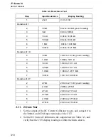
Table 3-4. Resistance Test
Step
Input Resistance
Display Reading
1
short
0.0 to 0.3
Ω
Decades of 1:
2
100
Ω
99.2 to 100.8
Ω
(plus 0 reading)
3
1k
Ω
994 to 1006
Ω
4
10 k
Ω
9.94 to 10.06 k
Ω
5
100 k
Ω
99.4 to 100.6 k
Ω
6
1 M
Ω
.994 to 1.006 M
Ω
7
10 M
Ω
9.79 to 10.21 M
Ω
Decades of 1.9:
2
190
Ω
188.7 to 191.3
Ω
(plus 0 reading)
3
1.9 k
Ω
1889 to 1911
Ω
4
19 k
Ω
18.89 to 19.11 k
Ω
5
190 k
Ω
188.9 to 191.1 k
Ω
6
1.9 M
Ω
1.889 to 1.9111 M
Ω
7
19 M
Ω
18.61 to 19.39 M
Ω
Decades of 2.7:
2
270
Ω
268.3 to 271.7
Ω
(plus 0 reading)
3
2.7 k
Ω
2685 to 2715
Ω
4
27 k
Ω
26.85 to 27.15 k
Ω
5
270 k
Ω
268.5 to 271.5 k
Ω
6
2.7 M
Ω
2.685 to 2.715 M
Ω
7
27 M
Ω
26.45 to 27.55 M
Ω
3-11. DC mA Test
1.
Set the output of the DC Current Calibrator to zero, and connect it to
the 300mA and COM input terminals of the UUT.
2.
Set the DC Current Calibrator to the output shown in Table 3-5, and
verify that the UUT display reading is within the limits shown.
Summary of Contents for 77 Series III
Page 5: ...77 Series III Service Manual iv...
Page 7: ...77 Series III Service Manual vi...
Page 11: ...77 Series III Service Manual 1 2...
Page 17: ...77 Series III Service Manual 1 8...
Page 19: ...77 Series III Service Manual 2 2...
Page 25: ...77 Series III Service Manual 2 8...
Page 27: ...77 Series III Service Manual 3 2...
Page 39: ...77 Series III Service Manual 3 14...
Page 43: ...77 Series III Service Manual 4 2...
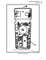
Page 50: ...List of Replaceable Parts Parts Lists 4 4 9 FLUKE 77 3 4001 aaa06f eps Figure 4 2 A1 Main PCA...
Page 51: ...77 Series III Service Manual 4 10 FLUKE 77 3 4001 aaa07f eps Figure 4 2 A1 Main PCA cont...
Page 52: ...5 1 Chapter 5 Schematic Diagrams...
Page 53: ...77 Series III Service Manual 5 2...
Page 55: ...77 Series III Service Manual 5 4 FLUKE 77 3 4001 aaa06f eps Figure 5 1 A1 Main PCA...
Page 56: ...Schematic Diagrams 5 5 5 FLUKE 77 3 4001 aaa07f eps Figure A1 Main PCA cont...

