


Theory of Operation
Detailed Description
2
2-7
AC
AC
AC
AC
AC
FILTER
FILTER
R10
C11
C5
C6
C8
C7
C9
+
+
R18
R19
R17
R9
16
17
28
26
39
40
27
44
45
10
9
8
46
47
INPUT
DIGITAL
SECTION
Z1
Z1
+
+
+
+
+
INT
DE-INT
REF
REF
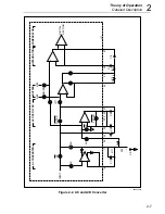
AC CONVERTER
ACTIVE FILTER
BUFFER
INTEGRATOR
COMPARATOR
U1
aaa03f.eps
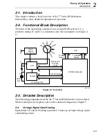
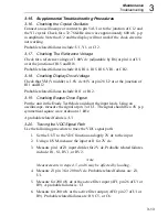
Figure 2-2. AC and A/D Converter
Summary of Contents for 77 Series III
Page 5: ...77 Series III Service Manual iv...
Page 7: ...77 Series III Service Manual vi...
Page 11: ...77 Series III Service Manual 1 2...
Page 17: ...77 Series III Service Manual 1 8...
Page 19: ...77 Series III Service Manual 2 2...
Page 25: ...77 Series III Service Manual 2 8...
Page 27: ...77 Series III Service Manual 3 2...
Page 39: ...77 Series III Service Manual 3 14...
Page 43: ...77 Series III Service Manual 4 2...
Page 50: ...List of Replaceable Parts Parts Lists 4 4 9 FLUKE 77 3 4001 aaa06f eps Figure 4 2 A1 Main PCA...
Page 51: ...77 Series III Service Manual 4 10 FLUKE 77 3 4001 aaa07f eps Figure 4 2 A1 Main PCA cont...
Page 52: ...5 1 Chapter 5 Schematic Diagrams...
Page 53: ...77 Series III Service Manual 5 2...
Page 55: ...77 Series III Service Manual 5 4 FLUKE 77 3 4001 aaa06f eps Figure 5 1 A1 Main PCA...
Page 56: ...Schematic Diagrams 5 5 5 FLUKE 77 3 4001 aaa07f eps Figure A1 Main PCA cont...


