Maintenance
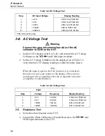
AC Voltage Test
3
3-9
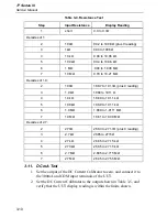
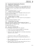
Referring to Table 3-4, set the Ohms Calibrator or Decade Resistor to the
resistance value indicated in steps 1 through 6. Verify that the display reading
is within the limits shown.
3-10. Diode
Test
1.
Set the UUT to the Diode Test function.
Note
On Fluke 5100 series calibrators, activate the 50
Ω
divider
override. On Fluke 5500A calibrators, lock voltage to the 33V
range.
2.
Apply an input from the DC Voltage Calibrator of +.090V dc to the
z
and COM input terminals of the UUT, and verify that the
beeper is on.
3.
Increase the DC Voltage Calibrator output to +.110V dc, and verify
that the beeper is off.
Summary of Contents for 77 Series III
Page 5: ...77 Series III Service Manual iv...
Page 7: ...77 Series III Service Manual vi...
Page 11: ...77 Series III Service Manual 1 2...
Page 17: ...77 Series III Service Manual 1 8...
Page 19: ...77 Series III Service Manual 2 2...
Page 25: ...77 Series III Service Manual 2 8...
Page 27: ...77 Series III Service Manual 3 2...
Page 39: ...77 Series III Service Manual 3 14...
Page 43: ...77 Series III Service Manual 4 2...
Page 50: ...List of Replaceable Parts Parts Lists 4 4 9 FLUKE 77 3 4001 aaa06f eps Figure 4 2 A1 Main PCA...
Page 51: ...77 Series III Service Manual 4 10 FLUKE 77 3 4001 aaa07f eps Figure 4 2 A1 Main PCA cont...
Page 52: ...5 1 Chapter 5 Schematic Diagrams...
Page 53: ...77 Series III Service Manual 5 2...
Page 55: ...77 Series III Service Manual 5 4 FLUKE 77 3 4001 aaa06f eps Figure 5 1 A1 Main PCA...
Page 56: ...Schematic Diagrams 5 5 5 FLUKE 77 3 4001 aaa07f eps Figure A1 Main PCA cont...

