Overview
Instrument Features and Capabilities
1
1-7
Fuse Compartment
SLOT CONFIGURATION
MODEL
XMT
LINK
RS-232
SERIAL
PORT
RCV
FLUKE CORPORATION
MADE IN USA
www.fluke.com
PATENTS PENDING
CAUTION:
FOR FIRE PROTECTION
REPLACE ONLY WITH
A 250V FUSE OF
INDICATED RATING
STANDBY
CHASSIS
GROUND
10/100 BASE T
ETHERNET
NOT FOR
CONNECTION
TO PUBLIC
TELEPHONE
SYSTEM
SERIAL NUMBER
2680A
2686A
100V- 240V
47Hz / 63Hz
100VA MAX
MAIN SUPPLY
NO INTERNAL USER SERVICEABLE PARTS.
REFER SERVICE TO QUALIFIED SERVICE PERSONNEL
WARNING:
TO AVOID
ELECTRIC SHOCK GROUNDING
CONNECTOR IN POWER CORD
MUST BE CONNECTED
FUSE
T 1/2A 250V
(SB)
1 2 3 4 5 6
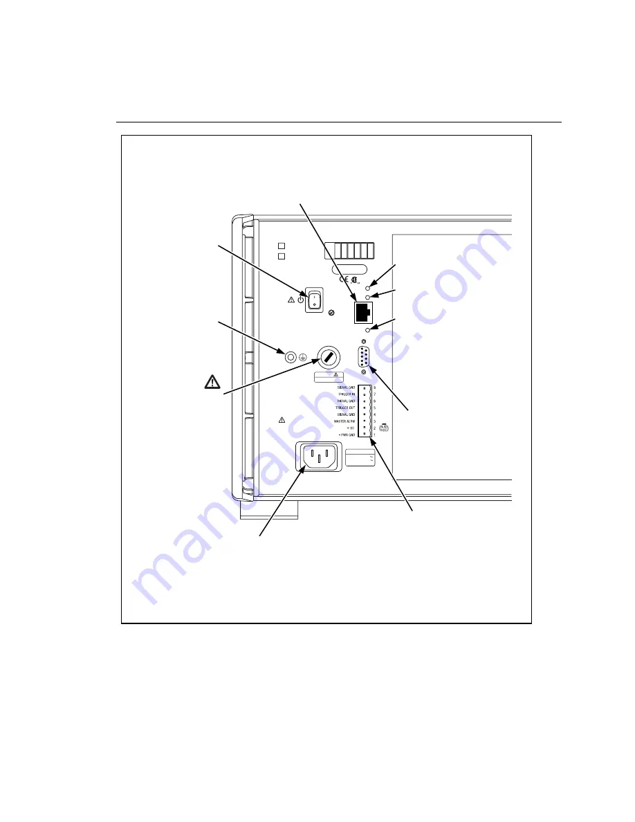
ALARM/TRIGGER I/O Connector.
Master Alarm output is logic low
when any channel is in alarm;
Trigger Out output is logic low for
nominal 125 ms start of any scan;
Trigger In input logic low triggers
scanning; DC PWR (dc volts input)
input is 9 to 45 V dc to power the
instrument.
AC Power Connector.
Connects to any line source
of 100 to 240 V ac (50/60 Hz).
Ground Terminal.
Connect to earth
ground when using
DC power.
Power Switch.
Supplies power to the
instrument (ac or dc
operation).
Ethernet 10/100BaseT Connector.
A RJ-45 connector that interfaces the
instrument with a 10/100BaseT
Twisted Pair Ethernet network. The
instrument automatically detects 10 or
100BaseT operation.
RS232
Serial Port
(for service use)
Ethernet Indicators.
XMT (transmit) blinks red for
instrument Ethernet transmissions.
RCV (receive) blinks red for any
Ethernet activity on the network.
LNK (link) lights red if 10BaseT is
operating, green if 100BaseT is
operating.
alg60f.eps
Figure 1-4. 2680A/2686A Rear Panel
Summary of Contents for 2680A
Page 8: ......
Page 14: ...2680A 2686A Users Manual vi ...
Page 20: ...2680A 2686A Users Manual 1 2 ...
Page 98: ...2680A 2686A Users Manual 2 62 ...
Page 196: ......
Page 228: ...2680A 2686A Users Manual A 32 ...
Page 236: ...2680A 2686A Users Manual C 4 ...
Page 242: ...2680A 2686A Users Manual D 6 ...
Page 274: ...2680A 2686A Users Manual 6 ...


