R and RX SLURRY Pump USER INSTRUCTIONS ENGLISH
71569242 03-11 (E)
Page 49 of 56
flowserve.com
®
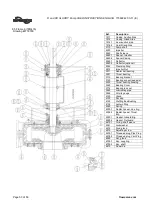
8 PARTS LIST AND DRAWINGS
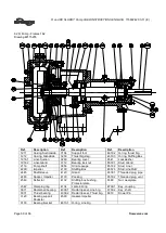
Figure 1
8.1 Frame 0 – 1.25R090
Drawing #2118793
Ref.
Description
1211
Casing, Suction Side
1212
Casing, Gland Side
1916.1
Liner-suction side
1916.2
Liner-Gland Side
2110
Pump shaft
2200
Impeller
2445
Shaft sleeve
2460.1
Spacer, Impeller
2460.2
Spacer-Casing
2540
Deflector
2542
Clamping Ring
2912
Impeller Nut
3011
Radial ball bearing, Line
brg.
3031
Thrust bearing
3110
Bearing bracket
3230
Thrust bearing housing
3260
Bearing Cover
3712
Bearing lock nut
3840
Lubricating pipe
3856
Oil site gauge
4120
Gland
4130
Packing
4132
Stuffing Box Bushing
4134
Lantern Ring
4260
Spring
4300.1
Radial lip seal, Line
bearing
4300.2
Radial lip seal, Thrust
Brg.
4590
Gasket, Sleeve
4610.1
O-ring, shaft sleeve
4610.2
O-ring, Thrust Brg Hsg
6541
Lockwasher
6572
Stud, gland
6576
Adjusting screw
6578.1
Threaded plug, Pipe
Plug
6578.2
Threaded plug, Vent
Plug
6580
Nut, gland
6700.1
Key, coupling
6700.2
Key, shaft
6810
Dowel Pin

