R and RX SLURRY Pump USER INSTRUCTIONS ENGLISH
71569242 03-11 (E)
Page 41 of 56
flowserve.com
®
6.10.6 Stuffing box
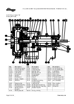
6.10.6.1 Stuffing Box 1.25R090
a) Place the glandside liner [1916.2] face down on a
clean work surface.
b) Install the stuffing box bushing [4132] onto the
liner.
The fit of the bushing is interference in order
to hold the liner and bushing together and to ensure a
seal.
c) Orient the flush ports in the bushing in line with
the discharge neck and flange.
d) Place the casing [1212] on the work surface with
volute section facing up.
e) Lift liner [1916.2] and install into casing [1212].
6.10.6.2 All sizes 2.5R and larger
a) Install the gland studs [6572] using Loctite grade A
or equivalent into the stuffing box [4130 or 4132].
Install the square head plugs [6578] in the stuffing
box as required using pipe sealant.
b)
Install the shaft sleeve onto the shaft. The hock
type sleeve must be seated against the shaft
shoulder. Application of Loctite is not necessary
as impeller tightening torque during operation is
sufficient to ensure sleeve rotation.
6.10.6.3 Standard packing-Frames 1-6
a) Place the glandside liner stud side up on a clean
work surface.
b) Install appropriate studs. The inner studs are
longer to mount the loose stuffing box [4132].
c) Lift the gland side casing [1212] and lower onto
the liner.
d) Secure outer studs with washers and hex.nuts.
e) Install the protector plate [4132] in the bore of the
casing and seat against the liner.
f) Install o-ring into face of stuffing box [4132]. Use a
small grease to hold the o-ring.
g) Install the stuffing box into the casing and align
the studs.
The flush ports be need to be orientated.
Review installation for any particulars. Normally the
ports will be aligned at 2 o’clock and 4 o’clock.
h) Secure with washers and nuts.
6.10.6.4 Gland Side Casings
6.10.6.4.1 All sizes
a) Lift the casing [1212] and install to the pedestal
[3120].
b) Secure casing to pedestal.
6.10.6.4.2 Frame 6 only
The babbit fits of the glandside casing to the
pedestal and to the stuffing box are loose. It is
necessary check the concentricity of the stuffing box
and the shaft with dial indicators or feeler gauges. If
necessary loosen studs and reposition stuffing box
and or the gland side casing. These parts may be
dowelled for subsequent maintenance.
Pedestal:
a) After alignment has been achieved, retighten
bolts.
b) The pedestal has been predrilled for 2 #8 tapered
dowel pins. Drill and ream the casing/pedestal
using the pilot holes in the pedestal as a jig.
#8 tapered dowels are nominally 12.7mm
(0.500in.) with 0.0208 (mm/mm or in./in.) taper.
c) Fit dowels and ensure all bolts are secure.
Stuffing box:
a) When centered, tighten bolts and remove gland
side casing.
b) The stuffing is predrilled 7.94mm (0.3125 in.) for
two dowel pins, it will be necessary to re-drill
stuffing box and casing together. Drill for a 3/8”
straight dowel.
c) Fit dowels and retighten all nuts.
d) Reassemble casing to pedestal.
6.10.6.5 Optional expeller seal-frame 1 &2
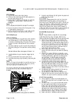
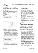
a) Assemble the stuffing box [4100] over the sleeve
[2445] and into the bearing frame [3130] register.
Orient the grease fitting to suit the installation. Note
that if the optional solid gland with lip seal design is
used, it must be installed first.
b) Install O-ring onto the expeller stuffing box. Install
expeller wearplate [1915] onto the stuffing box.
Some units may be built with a 1 pc stuffing
box/wearplate. In this cause this step will be
eliminated.
c) Install the expeller [2250] over the shaft sleeve.
Expeller should seat against the sleeve shoulder
but be clear of the expeller wearplate [1915].
Adjust the shaft [2110] forward to ensure that the
expeller [2250] when installed will not bind against
the stuffing box head [4100].
d) Install gasket [4590] over expeller to face of
stuffing box [4100].
e) Install expeller housing [4110] to stuffing box
[4132], clamp in place.


