


2001 Peristaltic Pump O&M Manual
40
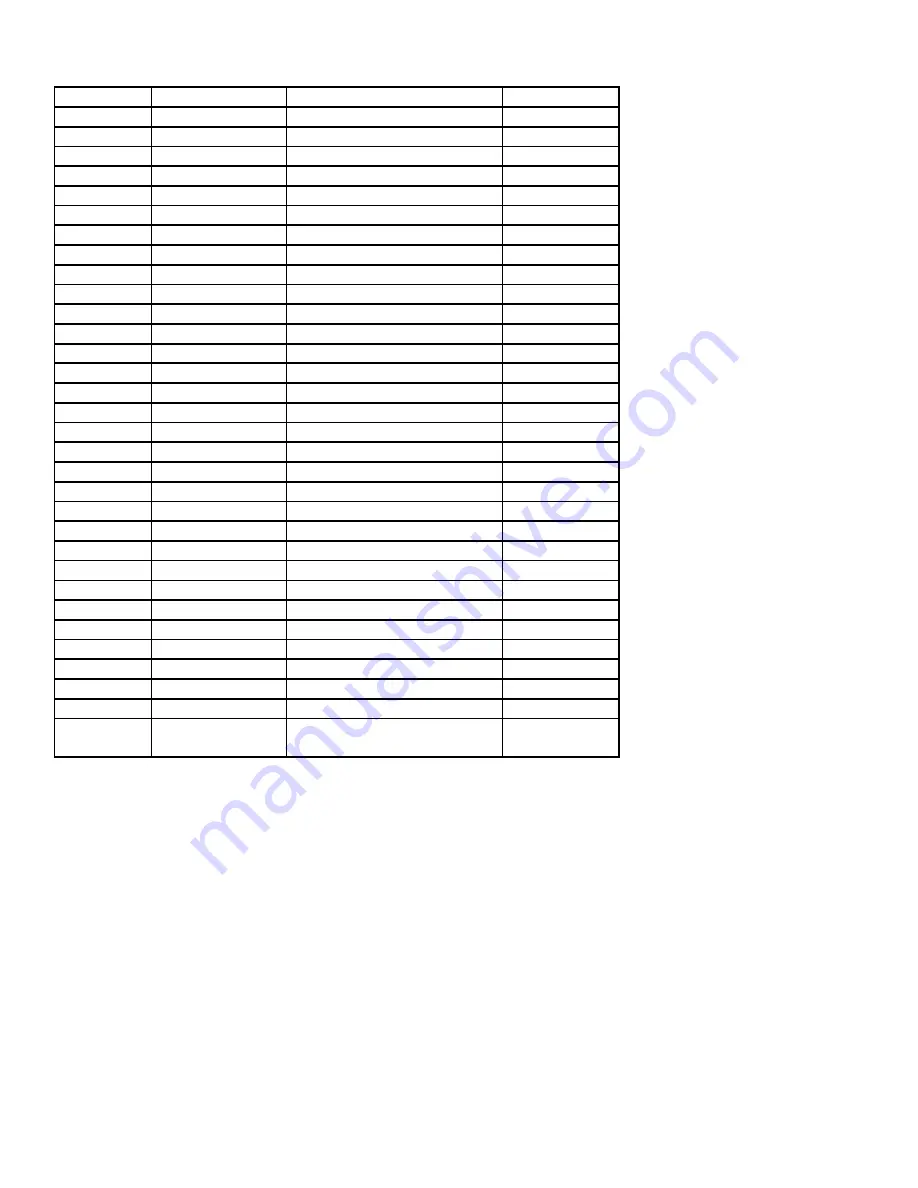
TB5 MAX
60.00 Hz
100% Hz
41
AIN FLTR
0.02 SEC
0.02 SEC
42
TB10A OUT
NONE
-
43
@TB10A
60.00 Hz
NONE
44
TB10B OUT
NONE
-
45
@TB10B
125 %
-
47
TB13A
NONE
4-20 mA
48
TB13B
NONE
-
49
TB13C
NONE
-
50
TB13D
EXT FAULT
-
52
TB14 OUT
NONE
AUTO/MAN
53
TB15 OUT
NONE
-
54
RELAY
NONE
-
55
TB5B LOSS
FAULT
SP#4
57
SERIAL
DISABLE
-
58
ADDRESS
30
-
61
PASSWORD
0019
-
63
SOFTWARE
(N/A)
-
64
MONITOR
ON
OFF
65
PROGRAM
RESET 60
MAINTAIN
66
HISTORY
MAINTAIN
-
70
PID MODE
OFF
-
74
PID FB
TB5A
-
75
FB @ MIN
0.00%
-
76
FB @ MAX
100.00%
100
77
P GAIN
5.00%
-
78
I GAIN
0.0 SEC
-
79
D GAIN
0.0 SEC
-
80
PID ACC
30.0 SEC
-
81
MIN ALRM
0.0%
-
82
MAX ALRM
0.0%
-
96
LANGUAGE
ENGLISH
-
99
FAULT
HISTORY
(NA)
-
Note 1: See 4.10.3 Description Of Programming Parameters, Step #19.
Flomotion Systems, Inc. 2001H SERIES
Pg. 20


