


2-wire cable from the unit to the vessel's battery or
distribution panel.
• Raymarine recommends a
minimum
wire gauge
of 18AWG (0.82 mm
2
) for any length of cable
extension.
• For all lengths of extension to the power cable,
ensure there is a continuous
minimum
voltage
at the product’s power connector of 10.8 V with a
fully flat battery at 11 V.
Important:
Be aware that some products in
your system (such as sonar modules) can create
voltage peaks at certain times, which may impact
the voltage available to other products during the
peaks.
Power distribution
Recommendations and best practice.
• The product is supplied with a power cable. Only
use the power cable supplied with the product. Do
NOT use a power cable designed for, or supplied
with, a different product.
• Refer to the
Power connection
section for more
information on how to identify the wires in your
product’s power cable, and where to connect them.
• See below for more information on implementation
for some common power distribution scenarios.
Important:
When planning and wiring, take into
consideration other products in your system, some
of which (e.g. sonar modules) may place large
power demand peaks on the vessel’s electrical
system.
Note:
The information provided below is for
guidance only, to help protect your product. It
covers common vessel power arrangements, but
does NOT cover every scenario. If you are unsure
how to provide the correct level of protection,
please consult an authorized Raymarine dealer or
a suitably qualified professional marine electrician.
Implementation — direct connection to battery
• The power cable supplied with your product may
be connected directly to the vessel's battery, via a
suitably rated fuse or breaker.
• The power cable supplied with your product may
NOT include a separate drain wire. If this is the
case, only the power cable’s red and black wires
need to be connected.
• If the supplied power cable is NOT fitted with an
inline fuse, you MUST fit a suitably rated fuse or
breaker between the red wire and the battery’s
positive terminal.
• Refer to the inline fuse ratings provided in the
product’s documentation.
• If you need to extend the length of the power cable
supplied with your product, ensure you observe
the dedicated
Power cable extensions
advice
provided in the product’s documentation.
D13344-1
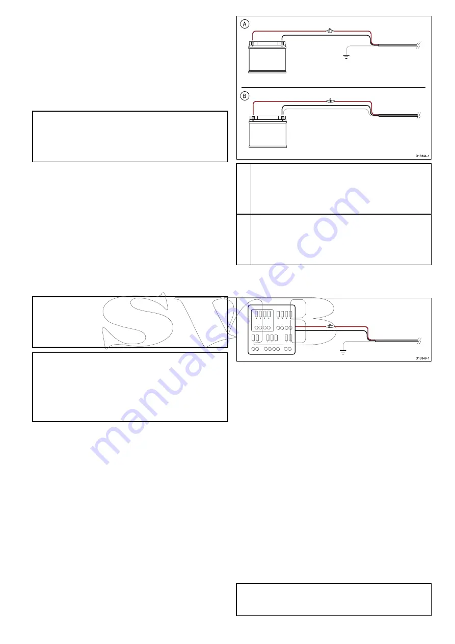
A
B
A
Battery connection scenario A: suitable for a vessel with
a common RF ground point. In this scenario, if your
product’s power cable is supplied with a separate drain
wire then it should be connected to the vessel’s common
ground point.
B
Battery connection scenario B: suitable for a vessel
without a common grounding point. In this case, if your
product’s power cable is supplied with a separate drain
wire then it should be connected directly to the battery’s
negative terminal.
Implementation — connection to distribution
panel
D13348-1
• Alternatively, the supplied power cable may be
connected to a suitable breaker or switch on the
vessel's distribution panel or factory-fitted power
distribution point.
• The distribution point should be fed from the
vessel’s primary power source by 8 AWG
(8.36 mm
2
) cable.
• Ideally, all equipment should be wired to individual
suitably-rated thermal breakers or fuses, with
appropriate circuit protection. Where this is not
possible and more than 1 item of equipment
shares a breaker, use individual in-line fuses
for each power circuit to provide the necessary
protection.
• In all cases, observe the recommended
breaker / fuse ratings provided in the product’s
documentation.
• If you need to extend the length of the power cable
supplied with your product, ensure you observe
the dedicated
Power cable extensions
advice
provided in the product’s documentation.
Important:
Be aware that the suitable fuse rating
for the thermal breaker or fuse is dependent on the
number of devices you are connecting.
Cables and connections
23
Summary of Contents for Raymarine CAM220IP
Page 2: ......
Page 4: ......
Page 6: ...6 CAM220IP...
Page 10: ...10 CAM220IP...
Page 18: ...3 9 Product dimensions CAM220IP 80 7 mm 3 18 in 99 2 mm 3 91 in D12985 1 18 CAM220IP...
Page 26: ...26 CAM220IP...
Page 27: ...Chapter 5 Mounting Chapter contents 5 1 Mounting the unit on page 28 Mounting 27...
Page 30: ...30 CAM220IP...
Page 36: ...36 CAM220IP...
Page 52: ...52 CAM220IP...
Page 53: ......


