background image

PTZ-35x140 

Quick Start Guide 427-0011-00-12 Version 100


similarly-equipped enemy observer, it is understandable that military interest in the image converter eventually 
faded. 


The tactical military disadvantages of so-called 'active’ (i.e. search beam-equipped) thermal imaging systems 
provided impetus following the 1939– 45 war for extensive secret military infrared-research programs into the 
possibilities of developing ‘passive’ (no search beam) systems around the extremely sensitive photon detector. 
During this period, military secrecy regulations completely prevented disclosure of the status of infrared-imaging 
technology. This secrecy only began to be lifted in the middle of the 1950’s, and from that time adequate thermal-
imaging devices finally began to be available to civilian science and industry.


How do Infrared Cameras Work?


Infrared energy is part of a complete range of radiation called the electromagnetic spectrum. The electromagnetic 
spectrum includes gamma rays, X-rays, ultraviolet, visible, infrared, microwaves (RADAR), and radio waves. The 
only difference between these different types of radiation is their wavelength or frequency. All of these forms of 
radiation travel at the speed of light (186,000 miles or 300,000,000 meters per second in a vacuum). Infrared 
radiation lies between the visible and RADAR portions of the electromagnetic spectrum. Thus infrared waves have 
wavelengths longer than visible and shorter than RADAR.


The primary source of infrared radiation is heat or thermal radiation. Any object which has a temperature radiates in 
the infrared portion of the electromagnetic spectrum. Even objects that are very cold, such as an ice cube, emit 
infrared. When an object is not quite hot enough to radiate visible light, it will emit most of its energy in the 
infrared. For example, hot charcoal may not give off light, but it does emit infrared radiation which we feel as heat. 
The warmer the object, the more infrared radiation it emits. 


Infrared cameras produce an image of invisible infrared or “heat” radiation that is unseen by the human eye. There 
are no colors or “shades” of gray in infrared, only varying intensities of radiated energy. The infrared imager 
converts this energy into an image that we can interpret. Several detector technologies exist; the sensors in the FLIR 
ThermoVision® cameras are of the latest solid state design, offering long life and fully automatic image 
optimization (contrast and gain). True thermal imagers should not be confused with infrared illuminator cameras 
that are often presented as simply “infrared cameras.” There are hundreds of low cost infrared illuminated cameras 
on the market at prices below $100. These cameras do not produce the same image because they do not detect heat. 
They operate in wavelengths near visible, and require an IR illuminator to provide an image. IR illuminators have 
very short range, and require a lot of power to see beyond 5 meters. 

Summary of Contents for PTZ-35x140

Page 1: ...PTZ 35x140 User s Guide 427 0011 00 10 Version 100 PTZ 35x140 with Foveus Users Guide 427 0011 00 10 Version 100...

Page 2: ...ltage range can cause permanent damage and will void the warranty Avoid pointing the device directly at extremely high intensity radiation sources such as the sun lasers arc welders etc This warning a...

Page 3: ...PTZ 35X140 4 QUICK START INFORMATION 5 PELCO D INTERFACE 6 NEXUS CONSOLE INTERFACE 9 PTZ 35X140 PHYSICAL INTERFACE 11 DIMENSION DRAWINGS 11 SYSTEM INTERFACE CABLE CONNECTOR 14 BREAK OUT CONNECTOR CABL...

Page 4: ...nt widely proliferated infrastructures The Foveus thermal imagery is provided as continually zoomed video from 20 horizontal field of view to less than 1 degree horizontal field of view The thermal im...

Page 5: ...output then plug a standard BNC cable to the connection labeled VIDEO P2 on the break out pigtail 4 If you intend to use the PELCO D Interface for remote control of the device attach a standard DB9 RS...

Page 6: ...WCS4 20 Master Power Supply will connect directly via connections labeled PTPWR and SYSPWR on the break out pigtail to the converter Connect the black leads to COM and the red leads to 24V Next adjus...

Page 7: ...ements Focus farther Far button FF 01 00 80 00 00 81 FF 01 00 81 Zoom In or Decreases FoV CW Joystick FF 01 00 20 00 00 21 FF 01 00 21 Zoom Out or Increases FoV CCW Joystick FF 01 00 40 00 00 41 FF 01...

Page 8: ...On Set DLTV as active For both commands and video 1 2 3 2 Aux Off Set IR as active For both commands and video 3 Aux On Toggle Plateau Values 3 Aux Off Toggle AGC Type 4 5 6 4 Aux On Autofocus One sh...

Page 9: ...m Administrator This is shown below Below are the steps to remote control and stream video using the Nexus Console 1 Double click on Nexus Icon on desktop and launch Nexus 2 Be sure to verify the IP a...

Page 10: ...channel by selecting the IR Camera Icon and right click to open Channel 1 for thermal as shown here 9 Next do the same for DLTV Camera to open Channel 2 for daylight 10 Now you are ready to use the PT...

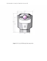
Page 11: ...1 00 10 Version 100 PTZ 35X140 PHYSICAL INTERFACE DIMENSION DRAWINGS The following figures show a dimensioned drawing of the PTZ 35x140 Remember to firmly secure unit and allow for device travel Figur...

Page 12: ...PTZ 35x140 User s Guide 427 0011 00 10 Version 100 Figure 2 PTZ 35x140 Dimension Drawing inches...

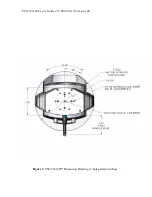
Page 13: ...PTZ 35x140 User s Guide 427 0011 00 10 Version 100 Figure 3 PTZ 35x140 Dimension Drawing w hole pattern inches...

Page 14: ...ive drab chromate over cadmium Contacts Pines Shell Style Cable plug Insert Position Keyring Figure 4 PTZ 35x140 Interface Cable Connector Function Pin Signal Name Function Pin Signal Name Power j Pow...

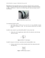
Page 15: ...nal ring leads for power Input voltage range 24 VDC 10 or 24 VAC 10 rms 50 60Hz Nominal static power consumption is 50W The red are positive and the black are common ground One BNC video connector is...

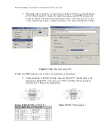
Page 16: ...ws EX rtsp 192 168 250 116 nfov Figure 8 Video Streaming using VLC Finally two DB9 connectors are used for communication as shown here Communication via RS 422 with the connector labeled P3 and the ot...

Page 17: ...740 000 pixels PAL and 630 000 pixels NTSC o FOV Horizontal 54 to 2 Optical o Focus Automatic o Iris Automatic o Shutter Automatic o Balance Automatic o IR cut filter Automatic o Image Stabilization...

Page 18: ...C to 55 C o Moisture IP 66 o Sand Dust MIL STD 810E Method 510 3 procedure II o Vibration MIL STD 810E Method 514 4 o Shock transportation 30g 11 msec o EMI EMC CE Class A FCC o Solar Thermal Loading...

Page 19: ...l IPA Procedure 1 Saturate a piece of the lens tissue with the water and drape it over the lens Let the surface tension of the water pull the tissue onto the lens surface and then drag the tissue acro...

Page 20: ...at while others passed so much heat that he risked eye damage after only a few seconds observation Herschel was soon convinced of the necessity of setting up a systematic experiment with the objective...

Page 21: ...uld receive credit as the originator Herschel s use of glass in the prism of his original experiment led to some early controversies with his contemporaries about the actual existence of the infrared...

Page 22: ...ters An English scientist Sir James Dewar first introduced the use of liquefied gases as cooling agents such as liquid nitrogen with a temperature of 196 C 320 8 F in low temperature research In 1892...

Page 23: ...rum Thus infrared waves have wavelengths longer than visible and shorter than RADAR The primary source of infrared radiation is heat or thermal radiation Any object which has a temperature radiates in...

Reviews: